




Installing a cable-suspended camera begins long before anyone tensions a wire rope or mounts a camera trolley. When I evaluate a proposed installation, I first examine the supporting structure, the complete load path, the operating environment, and the people who could enter the movement zone.
This cable camera anchor point installation guide explains how production teams can approach those decisions methodically while avoiding assumptions that can lead to structural failure, uncontrolled movement, or falling equipment.
Cable camera rigging is specialized work. Final anchor design, load calculations, hardware selection, installation, and approval should be handled by qualified professionals with experience appropriate to the structure and system involved.
What Is a Cable Camera Anchor Point?
An anchor point is the structural location where a cable, termination assembly, pulley, tensioning device, or related rigging component transfers force into a building, truss, tower, vehicle, ground system, or other support.
It is not simply the visible connector attached to the cable. The true anchorage includes the connector, supporting material, fasteners, welds, backing plates, structural members, and every component carrying force beyond the attachment.
A strong shackle cannot compensate for a weak beam, damaged truss, unsuitable concrete, undersized fastener, or unverified temporary structure. The complete load path must be assessed as one system.
Complete a Structural Site Assessment
Before selecting hardware, inspect the proposed cable route and both ends of the span. Record the distance, elevation difference, required camera path, nearby structures, minimum ground clearance, audience position, crew access, and emergency escape routes.
Before finalizing the anchor design, confirm that the selected system is appropriate for the span, payload, movement pattern, venue, and available support structures.
Reviewing and choosing the right cable camera system for productions at this stage helps prevent teams from designing anchors around equipment that is too heavy, too fast, or unsuitable for the location.
For complex environments, camera path generation for triangular mesh can help visualize the intended movement through a 3D representation of terrain, structures, and potential obstructions before installation begins.
A structural engineer may need to verify existing structures, unusual attachments, concrete capacity, welded connections, rooftop installations, temporary towers, or systems exposed to substantial dynamic and environmental forces.
Confirm Who Controls the Structure
Production teams should obtain approval from the property owner, venue, structural representative, or other responsible party before modifying or loading a structure. Existing rigging points should not be accepted without documentation showing their intended use, capacity, inspection status, and limitations.
Calculate the Entire Suspended Load
The payload includes much more than the camera body. Account for the lens, gimbal, remote head, batteries, media, transmitters, motors, mounting plates, trolley, drive components, control cables, safety restraints, and accessories.
Productions that require remote lens operation should also decide between manual vs wireless follow focus for filmmaking before calculating the final payload. Wireless focus motors, receivers, power cables, mounting brackets, and control units add weight and may alter the balance of the suspended camera package.
Calculations must also consider the cable itself, tensioning equipment, pulleys, terminations, hardware, and forces introduced at each anchorage. The lowest-rated component limits the system.
Static weight alone is not enough. Starting, braking, acceleration, emergency stopping, vibration, cable oscillation, trolley impact, uneven tension, and abrupt control inputs can increase forces beyond the resting load.
Account for Cable Tension and Sag
A cable stretched across a long span creates horizontal and vertical forces at its anchors. Reducing sag can sharply increase cable tension and anchorage demand. The installation should therefore use system-specific engineering calculations rather than visual judgment or a general rule of thumb.
Span length, elevation, cable type, pretension, payload, movement speed, temperature, intended sag, and termination method should all be included in the design.
Choose Rated and Compatible Rigging Hardware
Use identifiable, load-rated components intended for the direction and type of loading involved. These may include engineered brackets, beam attachments, shackles, wire-rope terminations, thimbles, slings, pulleys, turnbuckles, tensioners, and manufacturer-approved connectors.
Every component should have legible capacity information or traceable documentation. Hardware-store eyebolts, improvised clamps, unmarked connectors, knots in wire rope, or makeshift extensions are not substitutes for engineered rigging equipment.
Side loading, cross loading, point loading, and incorrect pin orientation can significantly reduce hardware performance. Follow manufacturer instructions for installation, tightening, alignment, inspection, and retirement criteria.
Install Independent Safety Redundancy
A backup restraint should not share the same likely failure point as the primary connection. Where the system design permits, attach secondary safety components to an independently verified structural location.
The restraint should be short enough to control movement following a primary failure but arranged so it does not interfere with normal operation. A safety cable does not make an unsuitable primary anchor acceptable.
Productions should also plan for partial failures involving a pulley, trolley, camera mount, termination, drive component, or accessory—not only complete anchor separation.
Control the Installation Area
Create an exclusion zone beneath the cable path, anchor points, tensioning equipment, and work-at-height areas. Only essential, authorized personnel should enter during installation, tensioning, testing, adjustment, or dismantling.
Federal rigging rules require equipment used for material handling to be inspected before use during each shift, with defective equipment removed from service. Rules covering suspended loads also emphasize planning routes that reduce worker exposure and keeping personnel clear of fall zones.
Crew responsibilities should be assigned before work begins. Identify who approves the structure, calculates loads, installs the system, verifies hardware, operates the trolley, watches the travel path, controls access, monitors weather, and initiates an emergency stop.
Inspect and Test Before Filming
Inspect the wire rope for corrosion, broken wires, crushing, kinks, bird-caging, heat damage, abrasion, deformation, and damaged terminations. OSHA requires a competent person to begin a visual inspection of applicable wire rope before each shift of use.
Confirm that fasteners are secured, pins are retained, shackles are correctly oriented, terminations are properly formed, tensioning devices are locked, cables clear sharp edges, and secondary restraints are installed.
Test the system without performers, spectators, or unnecessary crew inside the operating zone. Begin with slow, controlled movement and progress through the complete approved travel path. Test normal stops, communication procedures, operating limits, and the emergency stop under controlled conditions.
Monitor Weather and Changing Site Conditions
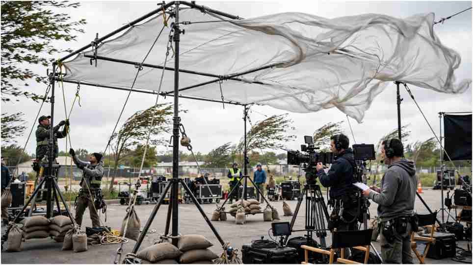
Outdoor cable systems may be affected by wind, lightning, rain, ice, heat, cold, soil movement, water intrusion, and temperature-related cable changes. Establish written operating limits using manufacturer requirements and engineering input.
Stop operations when conditions exceed approved limits or when unexpected cable movement, anchor displacement, unusual noise, loss of tension, communication failure, or control problems appear.
After severe weather, impact, overload, emergency stopping, structural modification, or suspected damage, the system should be removed from operation until qualified personnel complete the required reassessment.
Frequently Asked Questions
1. What is the most important step in a cable camera anchor point installation guide?
The most important step is verifying that the complete structure and load path can safely support calculated static, dynamic, and environmental forces.
2. Can an existing venue rigging point support a cable camera?
Only when its capacity, intended loading direction, condition, documentation, and structural suitability have been verified for the proposed system.
3. Should both cable anchors be identical?
Not necessarily. Each anchorage must be designed for its actual structure, geometry, loading direction, hardware, and calculated forces.
4. How often should the installation be inspected?
Inspect before each operating period and whenever weather, tension, hardware, structure, configuration, or system behavior changes.
Final Safety Perspective
When I plan a cable camera installation, I treat the anchor as part of an engineered system rather than an isolated attachment. I verify the structure, calculate every load, use traceable hardware, separate primary and secondary failure paths, restrict access, test the full route, and define clear shutdown conditions.
The most reliable installation is not the one that merely holds the camera during rehearsal. It is the one that remains controlled when movement, weather, equipment, or human decisions do not proceed exactly as expected.