



Roughly 80% of video loss in surveillance setups isn’t caused by camera hardware failure or network bugs—it stems directly from flawed cable deployment and physical termination errors.
Knowing how to wire cctv camera system setups correctly is the difference between an installation that runs continuously for a decade and one that drops frames during every summer heatwave or rainstorm.
For photographers, camera operators, and tech enthusiasts, signal transmission and line noise are familiar territory. Translating those principles to multi-camera surveillance requires mastering cable bandwidth, physical geometry, and clean power distribution.
IP Power Over Ethernet vs. Legacy Analog Architecture
Choosing your wiring topology dictates every cable you pull, the tools you need, and your overall signal integrity.
┌────────────────────────┐
│ Cat6 / Cat5e Cable │
┌──────────────┐ │ (Data + Power) │ ┌──────────────┐
│ PoE IP │────┼────────────────────────┼───>│ NVR Switch │
│ Camera │ │ Up to 328 ft (100m) │ └──────────────┘
└──────────────┘ └────────────────────────┘
┌────────────────────────┐
│ RG59 Coaxial (Video) │ ┌──────────────┐
┌──────────────┐ ├────────────────────────┤───>│ DVR BNC In │
│ Analog │────┤ 18/2 Wire (12V Power) │ ├──────────────┤
│ Camera │ └────────────────────────┘ │ Power Box │
└──────────────┘ └──────────────┘
Suggested Visual: A horizontal split-diagram showing a single Cat6 line connecting a PoE Camera to an NVR vs. a dual-shot RG59 Siamese cable splitting into BNC and power lead connectors.
| System Type | Primary Cable Standard | Max Distance Without Signal Boost | Transmission Method | Power Source |
| IP (Network) | Cat5e / Cat6 | 328 feet (100 meters) | Digital Packet Stream | PoE / PoE+ via Switch or NVR |
| Analog / HD-TVI | RG59 Siamese Coaxial | 750–1,000 feet | Uncompressed Analog Waveform | 12V DC / 24V AC External Box |
Digital IP (PoE) Systems
Network-based surveillance leverages Power over Ethernet (PoE, IEEE 802.3af/at standard), consolidating 48V DC power and high-throughput video data onto a single 8-conductor Twisted Pair cable. Category 6 (Cat6) copper is the preferred standard here. It isolates data pairs to eliminate internal crosstalk while handling high-bandwidth streams from 4K and multi-lens cameras.
Analog HD (Coaxial) Systems
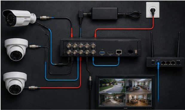
Legacy or retrofit architectures rely on RG59 Siamese cabling—a 95% copper-braided coaxial core paired with an adjacent 18/2 gauge power wire. While RG59 can push analog video over longer straight distances without latency, it lacks the modular flexibility, encryption, and visual clarity offered by raw IP video feeds.
Step-by-Step Field Installation Process
Executing a clean cable pull requires precise planning to prevent structural damage, unwanted signal attenuation, and environmental wear.
┌─────────────────┐ ┌─────────────────┐ ┌─────────────────┐ ┌─────────────────┐
│ 1. Path Mapping │ ──> │ 2. Structural │ ──> │ 3. Cable Pull │ ──> │ 4. Termination │
│ & Drill Points │ │ Penetration │ │ & Routing │ │ & Testing │
└─────────────────┘ └─────────────────┘ └─────────────────┘ └─────────────────┘
1. Path Mapping and Pre-Pull Calculation
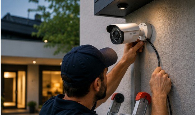
Begin your Indoor Arena Cable Camera Setup Guide by mapping your home run—the central path where all field cables converge at the Network Video Recorder (NVR) or Digital Video Recorder (DVR). Mark mounting points 10 to 15 feet above ground level. This placement ensures a 70-to-90-degree field of view while keeping hardware out of easy reach.
2. Structural Penetration
Drill entry points at a slight upward angle (roughly 5 to 10 degrees) from the exterior face inward. This angled path creates a natural drip loop that prevents rainwater from tracking down the jacket and penetrating the interior building envelope.
3. Cable Pulling and Mechanical Isolation
Feed cables through attics, soffits, or drop ceiling cavities using fiberglass fish rods or flexible steel fish tape.
- Maintain strict clearance: Keep low-voltage data cables at least 12 inches away from high-voltage 120V/240V AC electrical lines.
- Perpendicular crossings: When low-voltage and high-voltage lines must meet, cross them at a strict 90-degree angle to prevent electromagnetic interference (EMI) that causes video noise and packet loss.
- Bend radius control: Never bend Cat6 cable tighter than four times its outer diameter (roughly a 1-inch minimum bend radius) to preserve pair geometry.
If you are running camera rigs or specialized tracking platforms in dynamic capture environments, explore our cable camera anchor point installation guide for advanced structural rigging methods.
4. Termination and Hardware Handshake
Strip the outer jacket back 1 inch, sequence your conductors to the T-568B pinout standard, and crimp RJ45 connectors with a pass-through crimper. Plug the camera end into the housing drop and the central end into your PoE switch or NVR.
Essential Hardware and Tools
Before starting your run, gather these specialized low-voltage tools:
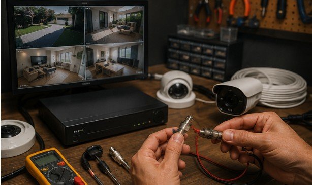
- Solid Copper Cat6 UTP Cable: Avoid Copper Clad Aluminum (CCA), which fails under PoE loads.
- RJ45 Pass-Through Connectors & Ratchet Crimper: For reliable 8P8C terminations.
- Fiberglass Fish Rods & Pull String: Essential for guiding cables through wall cavities and tight soffits.
- Step Drill Bit & Silicone Sealant: For clean exterior wall penetrations and weatherproofing.
- Low-Voltage Wall Plates & Junction Boxes: Protects internal wiring joints from strain and environmental exposure.
Advanced Routing: Weatherproofing, Conduits, and Cable Concealment
Exposed exterior cabling invites UV degradation, moisture ingress, and physical tampering. Exterior cable runs descending down building faces must be encased in Schedule 40 PVC or rigid EMT conduit.
Where cables enter outdoor junction boxes, seal the threads with Teflon tape and establish a downward drip loop directly below the entry gland. When running lines across open ground or driveways, bury Schedule 80 PVC conduit at least 18 inches deep (per National Electrical Code guidelines for low-voltage burial) to protect against lawn care equipment and soil settling.
For indoor spaces, routing cables through interior wall cavities or high-density crown molding tracks keeps your installation secure and clean. For an in-depth breakdown of interior routing methods, review our complete guide on how to hide security camera cables.
When designing mobile camera setups or production rigs, controlling hardware remotely requires a similar focus on physical infrastructure. Check out our technical review comparing manual vs wireless follow focus for filmmaking to see how physical controls stack up against wireless signal routing.
Edge Cases, Limitations, and Misconceptions
While low-voltage wiring seems straightforward, several real-world edge cases can derail an installation:
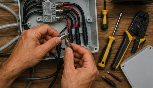
- The 328-Foot IEEE PoE Limit: Ethernet streams degrade sharply past 100 meters. For longer runs, install an inline PoE extender, run a dedicated fiber optic line with media converters, or power the camera locally.
- The Copper-Clad Aluminum Trap: Avoid cheap CCA (Copper-Clad Aluminum) wire. Aluminum has higher resistance than pure copper, which causes voltage drops, excessive heat under PoE loads, and brittle conductor snaps during tight pulls. Always insist on solid bare copper (OFC).
- Ground Loops in Analog Systems: Connecting analog cameras to different ground potentials across long coaxial runs creates ground loops—appearing as dark rolling horizontal bars across your screen. Solve this by powering cameras from a single central supply box or using ground loop isolators.
Frequently Asked Questions
1. How to do wiring for a CCTV camera?
Run a solid copper Cat6 cable from your NVR to the camera location. Strip the wire ends, terminate them with RJ45 connectors using the T-568B standard, plug one end into the camera, and connect the other to a PoE port.
2. How are CCTV cameras wired?
IP cameras use a single Cat5e/Cat6 Ethernet cable to transmit 48V PoE power and video data together. Analog systems use dual-strand RG59 Siamese cable—coaxial line for BNC video signals and 18/2 gauge wire for 12V power.
3. What is the best way to run wires for security cameras?
The cleanest method is routing Cat6 cables internally through attics, soffits, and wall cavities using fish rods. For exterior runs, enclose lines inside UV-rated PVC conduit and drill downward-slanted entry points with drip loops to block moisture.
4. How to set up a wired CCTV camera?
Mount the camera housing onto an exterior junction box. Route your Ethernet line to the NVR switch, crimp both ends, connect a monitor to the NVR’s HDMI port, and verify power and live video feeds across all channels.
Precision Infrastructure Yields Flawless Feeds
Treating security wiring with the same care as broadcast studio cabling guarantees a solid, low-maintenance installation. Measure your distances carefully, run solid bare copper lines, and seal every structural entry point. A clean, disciplined cable pull ensures your security system delivers sharp, uninterrupted video when it matters most.