





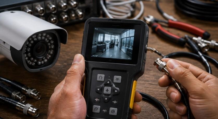
A cable can pass a continuity test and still fail with real video. That is the key fact behind how to test camera cable signal: continuity proves a path exists, but it does not prove the cable can carry clean SDI, HDMI, Ethernet, or analog video at the required bandwidth. Fluke Networks draws the same distinction in network testing: wire-map verification finds opens, shorts, reversals, and split pairs, while qualification is needed to prove performance.
Identify the Cable Before You Test It
A BNC cable may carry analog video or SDI; RJ45 may carry Ethernet and PoE; HDMI needs a different test path.
Broadcast SDI normally uses 75-ohm video coax. Belden’s current broadcast range includes 75-ohm cables rated for high-bandwidth video applications up to 12 GHz. That matters because a cable can be electrically continuous while connector damage, excessive loss, or impedance problems still make a high-rate SDI feed unstable.
| Cable type | Best first test | What it checks |
| BNC/coax | Continuity + short test | Center conductor and shield |
| Cat5e/Cat6 | RJ45 wire-map tester | Pair termination |
| PoE Ethernet | PoE/network tester | Power plus network path |
| HDMI | Known-good source/display | Operation at target format |
A Five-Step Camera Cable Test
1. Inspect Connectors and Strain Points
Check the first few inches behind every connector. Look for bent BNC center pins, loose barrels, crushed coax, damaged RJ45 latches, oxidized contacts, or sharp kinks.
Gently flex the cable near each connector while testing. On moving installations, a cable camera anchor point installation guide can help separate signal faults from routing or strain problems.
2. Test Coax Continuity With Power Off
Disconnect both ends before using continuity mode. Fluke instructs users to perform continuity testing on a de-energized circuit.
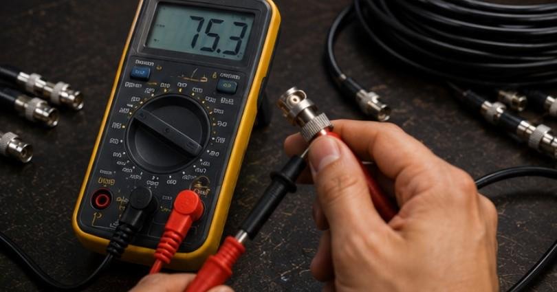
For BNC coax, test the center conductor end to end. The meter should indicate continuity. Then test the outer shield end to end; it should also show continuity.
Finally, test between the center pin and outer shell. There should not be continuity. A beep there suggests a short.
This is useful for analog CCTV and SDI cables, but a successful continuity test does not certify video performance.
3. Verify Power at the Camera End
If the camera receives separate DC power, measure voltage at the camera end, not only at the power supply. Cable resistance or poor connectors can create voltage drop.
Do not assume every camera should read the same voltage. Compare the reading with the manufacturer’s specified input range.
For PoE cameras, use a PoE-aware tester or network tester. IEEE material describes PoE reaching roughly 44–57 V after successful device detection, and Axis specifies 44–57 V DC for products using IEEE 802.3af/at PoE.
4. Test Ethernet Cables With a Wire Mapper
For Cat5e or Cat6, a proper wire-map test can identify opens, shorts, crossed pairs, reversed pairs, and split pairs.
A pass on a basic tester still does not prove the cable can sustain the required network speed. Fluke separates verification from qualification and certification because performance faults can exist even when continuity is correct.
For long moving-camera runs, cable camera vs drone for cinematic shots is also worth comparing when distance, control, and operating environment affect the design.
5. Prove the Actual Video Signal
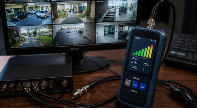
The final test should be active. Connect the suspect cable between a known-good camera or signal generator and a known-good monitor, recorder, switcher, or receiver.
Test at the exact resolution and frame rate you intend to use. If SDI works at HD but drops at a higher data rate, the issue may be cable loss, length, connector quality, or impedance rather than a complete break.
For HDMI, substitution is especially practical. HDMI Licensing Administration says certified Premium High Speed HDMI cables are tested for 18 Gbps bandwidth and electromagnetic-interference requirements. That is a good illustration of why digital cables need more than continuity to prove performance.
Why a Multimeter Is Only the First Layer
A multimeter can find an open conductor, a broken shield, a short, or an unexpected voltage. It cannot tell you whether a cable meets the signal-integrity requirements of a high-speed format.
Fluke’s certification guidance lists insertion loss, return loss, crosstalk, and related measurements separately from simple continuity and wire mapping.
A cable may pass on the bench yet fail after adding an extension, another connector, or a higher-resolution signal. Before replacing hardware, check the whole chain; choosing the right cable camera system for productions also means considering transport, control, routing, and distance together.
Fast Troubleshooting Checklist
Start by replacing the suspect cable with a known-good one. If the problem disappears, test the original cable off the rig.
Then inspect connectors, test continuity or wire mapping, verify far-end power, and test the real video format. For difficult Ethernet faults, higher-level testers can report cable length and distance to a fault; Fluke’s CableIQ platform supports coax and twisted-pair troubleshooting for opens and shorts.
If a cable passes basic tests but still fails intermittently, replace it or use a professional analyzer. An intermittent cable is not worth risking a take.
Frequently Asked Questions
1. How to check if a camera cable is working?
Inspect the connectors, test continuity or wire mapping, verify power if required, then connect a known-good camera and monitor to confirm an actual signal.
2. How do I test my cable signal?
Use the tool suited to the cable: a multimeter for basic coax checks, an RJ45 tester for Ethernet wiring, and a test monitor or analyzer for the real signal.
3. How to check if a cable line is active?
Use an appropriate tester at the far end. Check link and PoE status for Ethernet, or use a compatible monitor or signal analyzer for video coax.
4. Can you test coax cable signal with a multimeter?
Partly. A multimeter can test continuity, shield integrity, shorts, and some power conditions. It cannot prove that coax meets the bandwidth requirements of SDI or other high-frequency video.
The Rule That Prevents Wasted Troubleshooting
The best answer to how to test camera cable signal is not simply “use a multimeter.” Test the cable at the level where the failure occurs: continuity first, power and wiring next, then the real video or network link. A cable that beeps is connected. A cable that carries the required signal reliably is ready for production.