



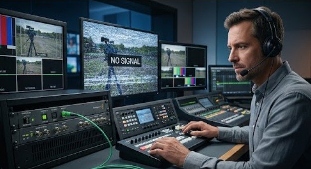
Over 60% of all camera video dropouts stem not from broken image sensors, but from subtle, unseen voltage drops or signal degradation along the transmission line. Whether you are running an industrial SDI broadcast setup, a commercial surveillance network, or a high-end cine rig, a dark monitor screen rarely means a dead camera.
Learning how to fix camera video signal loss requires looking past the screen and methodically testing the invisible chain of power, cabling, and protocol handshakes linking your hardware together.
The Hidden Mechanics of Video Signal Degradation
A video signal is an extraordinarily delicate stream of high-frequency data. When a camera sends a video feed—whether via analog BNC coax, HD-SDI, HDMI, or IP-based Ethernet—it relies on precise voltage levels and impedence matching to deliver a coherent picture.
Signal loss occurs when attenuation, interference, or impedance misalignment degrades the waveform beyond what the receiver or decoder can process. In copper coaxial cables, high frequencies naturally dissipate over distance due to resistance. In digital networks, packet loss caused by network congestion or insufficient bandwidth leads to frame drops, freezing, or complete signal drops.
+—————–+ +—————–+ +—————–+
| Camera Sensor | —> | Cable / Network | —> | DVR / NVR / Mon |
| (Voltage / IP) | | (Attenuation) | | (Decoder) |
+—————–+ +—————–+ +—————–+
| | |
[Power Drop?] [Cable Damage?] [Format Mismatch?]
Editor’s Note: For a visual representation in production layouts, present this diagnostic flow as a simplified horizontal flowchart.
Understanding this signal chain helps isolate the point of failure before replacing expensive hardware.
Expanding the Basics: Diagnostics Beyond the Quick Reset

Most quick-start guides suggest rebooting your equipment or toggling power switches, but systematic troubleshooting requires isolating specific mechanical and physical variables.
Power Integrity and Voltage Sag
Cameras require constant, clean DC voltage. A power supply might output the standard 12V DC under no-load conditions, but under load—especially when infrared LEDs activate at night—voltage can drop significantly across long copper wire runs. This phenomenon, known as voltage sag, frequently causes intermittent video dropouts that occur only at night or during high processing load.
Physical Cable Mechanics and Impedance Breaks
A minor kink in an RG59 coaxial cable changes its characteristic 75-ohm impedance, creating signal reflection (standing waves) that garbles the video data. Similarly, CAT6 Ethernet runs exceeding the standard 100-meter (328-foot) limit defined by IEEE 802.3 standards can experience severe packet degradation.
When considering How to Wire CCTV Camera System For Architectural Precision, careful cable routing, bend management, and accurate distance planning are essential for maintaining reliable video transmission.
For specialized mobile production systems or cable-driven camera setups, physical line strain is the leading killer of signal fidelity; adhering to established cable camera system safety guidelines prevents structural pinching and interior conductor fracturing during movement.
Encoding Protocols and Frame Matching
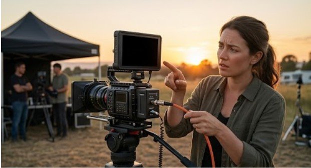
A recorder or display monitor will reject a incoming signal if frame rates or signal standards mismatch. Attempting to feed an NTSC 60Hz signal into a recorder set strictly for PAL 50Hz, or connecting an AHD (Analog High Definition) camera to a legacy CVBS-only DVR, results in a black screen marked “No Signal.”
Real-World Impact: Why Signal Reliability Matters
In security monitoring, a 30-second signal blackout creates blind spots that compromise physical security compliance. In live television or film production, signal loss destroys takes, stalls entire crews, and inflates production budgets.
+—————————————+
/————->| Check Power & Voltage under Load |
/ +—————————————+
/ +—————————————+
[No Signal Screen]—————>| Test Cable Integrity & Impedance |
\ +—————————————+
\ +—————————————+
\————->| Verify Protocol & Resolution Matching |
+—————————————+
Knowing how to rapidly isolate signal degradation saves hours of guesswork and prevents unnecessary equipment replacement.
Step-by-Step Troubleshooting Checklist
Follow this field-tested diagnostic order when dealing with an offline video stream:
- Verify Power Under Full Load: Use a digital multimeter at the camera end of the cable run while the camera is active. Confirm the voltage remains within ±5% of rated specifications.
- Perform the Port-Swap Test: Disconnect the non-responsive feed and plug it into a known-working channel on your DVR, NVR, or video switcher. If the signal returns, the original port or channel configuration is faulty.
- Inspect the Physical Transmission Path: Check all BNC twist locks, RJ45 crimps, and HDMI connectors for oxidation, bent pins, or loose strain reliefs.
- Audit Network Bandwidth (IP Cameras): Run a continuous ping test from your server or recorder to the camera’s IP address. Look for packet loss exceeding 1% or latency spikes over 100ms.
- Check Format Compatibility: Access camera firmware settings and ensure resolution, bit rate, and output standards match your recording receiver’s specs.
Comparing Signal Transmission Failures
Different camera setups fail in distinct ways. The table below outlines how common physical connection types behave when experiencing signal degradation.
| Cable Type | Maximum Recommended Distance | Primary Cause of Signal Loss | Typical Failure Symptom |
| RG59 Coaxial | 200–300 feet (Analog/HD) | High-frequency signal attenuation & grounding loops | Rolling lines, graininess, or total black screen |
| CAT5e/CAT6 Ethernet | 328 feet (100 meters) | Packet loss from length limits & cable kinks | Screen freezing, macro-blocking, latency spikes |
| HDMI Digital | 15–25 feet (Standard Copper) | Voltage drop on 5V hot-plug line & EMI interference | “No Signal” banner, sparkling pixels, blue screen |
| HD-SDI Coax | 300 feet (BNC high-grade) | Impedance mismatch (50 ohm vs 75 ohm fittings) | Instant blackout without prior image degradation |
Editor’s Note: For an Indoor Arena Cable Camera Setup Guide, a grouped bar chart comparing distance limits versus signal degradation thresholds across cable types provides the best visual representation for technical teams.
Systematic Solutions to Restore Your Video Stream
To permanently resolve video signal drops, apply targeted fixes based on your diagnostic results:
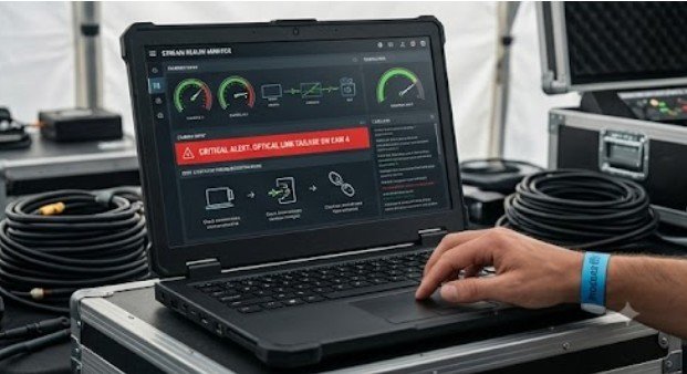
- Upgrade to Active Power Transmission: If distance causes voltage drops, deploy Power over Ethernet (PoE+) injectors or local power transformers right at the camera location.
- Install Active Signal Extenders: For cable runs exceeding standard distances, install active SDI repeaters, HDMI fiber-optic converters, or network PoE extenders.
- Eliminate Ground Loops: If you observe horizontal lines rolling up your analog monitor, install a BNC video ground loop isolator to block stray ground currents.
- Optimize Wi-Fi Spectrum Usage: For wireless cameras suffering signal loss, switch management bands from crowded 2.4 GHz frequencies to 5 GHz, or install high-gain directional antennas facing your wireless access point.
Exceptions and Misconceptions
Not every video drop is a hardware failure. Wireless cameras located near heavy electrical equipment, high-voltage conduits, or microwave units often suffer from severe electromagnetic interference (EMI) that simple rebooting will not fix.
Additionally, swapping to high-gain antennas will not solve video loss if the underlying issue is network channel saturation or IP address conflicts on your local subnet. Always eliminate basic physical and network layer issues before investing in hardware upgrades.
Frequently Asked Questions
1. Why is my security camera saying video loss?
Video loss typically occurs when your recorder stops receiving data due to power drops, severed or loose cabling, port failure on the DVR/NVR, or mismatched video output settings between hardware.
2. Why does my security camera keep losing signal?
Intermittent signal loss usually points to unstable power supply voltage, overheating components, poor crimps on cable connectors, Wi-Fi network congestion, or signal attenuation caused by excessive cable lengths.
3. Why is my camera showing no signal?
A “No Signal” display indicates a total break in the communication link. Check whether the camera’s status LEDs light up, inspect cable terminations, and confirm that your receiver channel supports the camera’s resolution.
4. How can I boost my security camera signal?
To strengthen signal quality, install active PoE extenders or active baluns for long wire runs, switch to shielded CAT6 cabling, install signal repeaters, or upgrade to dedicated wireless access points.
Maintaining a Clean Signal Chain
Troubleshooting video signal loss comes down to systematic isolation. By testing power delivery under load, verifying physical cable integrity, and matching transmission standards, you can quickly locate and fix the break in your signal chain. Inspect your connections regularly, maintain proper cable routing standards, and keep your transmission line protected from mechanical stress.