



I walked into the facility expecting a difficult filming day, but the first location survey revealed a problem bigger than our crew had anticipated. The director wanted a smooth tracking shot through an active production area filled with steel columns, overhead pipes, vibrating machinery and narrow walkways. A conventional dolly could not fit, handheld footage looked unstable, and attaching equipment to the building without approval was out of the question.
For me, solving camera rigging challenges inside an industrial location meant finding a way to protect the creative idea without compromising the facility, equipment or people working around us. Our eventual solution came from careful surveying, a rejected first design and a compact remote rig built specifically for the environment.
The Shot Our Production Needed
The planned sequence had to begin with a wide view of the production line before moving beside an operating machine and finishing on a detailed component. It needed to feel continuous, controlled and close to the action.
Unfortunately, the available route was too narrow for a standard track. A camera operator walking backward would have entered a restricted working area, while a crane required more headroom than the location provided. Machinery vibration also travelled through the floor, making a normal tripod unsuitable for the moving shot.
The final camera package included the body, compact lens, remote focus motor, wireless video transmitter, mounting plate, power supply and control cables. Although wireless charging was considered for reducing exposed connections, the continuous power demands and metal-heavy environment made a secured wired supply more dependable.
Looking only at the camera’s weight would have produced an inaccurate payload calculation, so every component was included before the support system was selected.
What the Technical Survey Revealed
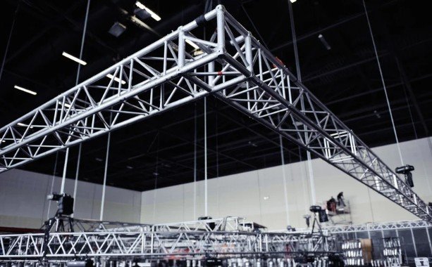
A detailed technical survey became the most important part of pre-production. We measured the proposed camera route, checked overhead clearance and identified doors, emergency exits and active walkways that had to remain unobstructed.
The facility representative also showed us which surfaces were part of operating machinery and which structural areas could not be touched. Pipes, guardrails, cable trays and equipment housings were immediately excluded as possible mounting points. Even when an object appeared strong, we did not treat appearance as proof of structural capacity.
Other complications included airborne dust, intermittent electrical interference, changing light levels and continuous low-frequency vibration. Wireless video performance was tested at several positions because metal walls and machinery could weaken or reflect the signal.
The First Rigging Plan Failed
Our original concept used one main support arm attached near the required camera position. It looked compact and allowed quick framing adjustments, but the test exposed two serious weaknesses.
First, the long arm created leverage that amplified small movements at the attachment point. Second, the machinery produced vibration at a frequency the camera stabilizer could not fully correct. The resulting footage showed subtle horizontal movement that became distracting on a large monitor.
Building a Compact Multi-Point Camera Rig
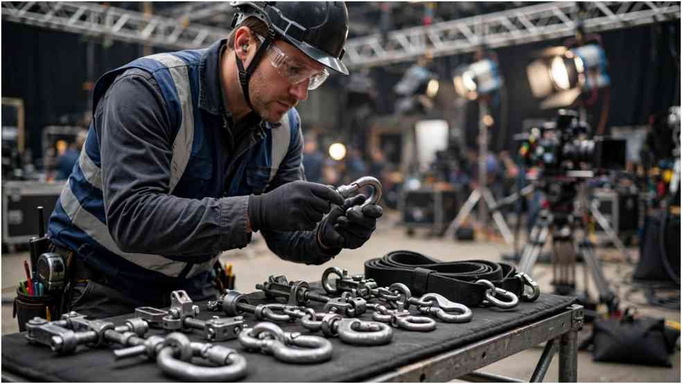
The revised design used a rigid modular frame supported from multiple approved points. Spreading the load reduced flex and prevented the camera package from depending on a single connection. Triangulation strengthened the assembly without creating a wide structure that interfered with the production line.
We reduced the payload by selecting a lighter lens, relocating the main power source and removing unnecessary accessories. A properly matched vibration-isolation layer was placed between the frame and remote head. It reduced high-frequency movement while remaining firm enough to prevent the camera from floating during acceleration and stopping.
Adding Redundancy and Cable Control
An independent secondary restraint was installed separately from the main support. It was positioned to limit movement if the primary system experienced a failure. The restraint did not make an unsuitable primary mount acceptable; it served only as an additional protective measure.
Cables were secured at several points with controlled service loops near moving components. Nothing was allowed to hang into a walkway, rub against a sharp surface or transfer pulling force to a camera connector.
Remote monitoring allowed the operator, focus puller and director to remain outside the restricted area. It also reduced unnecessary movement around operating equipment.
Testing the Rig Before Recording
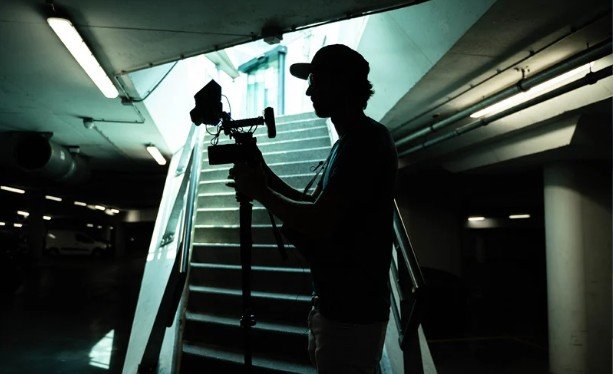
The crew began with a static inspection covering fasteners, connections, clearances, restraints and cable paths. Reference marks were added to selected fasteners so that unexpected rotation could be noticed between takes.
This staged process was central to solving camera rigging challenges inside an industrial location because industrial conditions can change after machinery starts. A support system that appears stable in a quiet building may react differently once motors, conveyors and ventilation equipment are running.
A designated person could stop the camera move immediately. Everyone understood the stop signal, who could issue it and when crew members were permitted to approach the rig.
The Result of the Final Setup
The completed system produced a stable tracking movement without blocking an aisle or placing an operator beside active machinery. The remote head provided small framing corrections, so the grip crew did not need to rebuild the support between takes.
Most of the footage was usable without aggressive stabilization. More importantly, the sequence was completed without unexpected rig movement, damaged equipment or disruption to the facility’s normal workflow.
Documenting the failed concept also gave the crew valuable information for future productions. It demonstrated that payload reduction, short support spans, triangulation and controlled testing could produce better results than simply adding heavier hardware.
Frequently Asked Questions
1. What makes camera rigging difficult in an industrial facility?
Restricted access, vibration, dust, noise, active machinery, limited headroom and protected building systems can all affect the design. Facility rules may also prohibit attaching equipment to surfaces that appear convenient.
2. How can crews reduce vibration in a camera rig?
Crews can shorten unsupported spans, reduce the camera payload, strengthen the frame and use vibration isolation matched to the equipment and vibration conditions. Testing remains essential.
3. Can a crew attach a camera to existing factory structures?
A structure should never be selected from appearance alone. Any proposed attachment must be reviewed by the facility and suitably qualified professionals for the specific load and application.
4. How should a remote industrial camera rig be tested?
Testing should progress from static inspection to controlled movement and then to realistic operating conditions. The rig and captured footage should be reviewed after every stage.
5. Why is solving camera rigging challenges inside an industrial location different from studio rigging?
A studio is designed to support production activity. An industrial facility has its own machinery, employees, restrictions and operating priorities, so the camera system must adapt without introducing new hazards or interrupting essential work.
Final Takeaways
I left the facility with a stronger reminder that a successful camera rig is not merely one that holds its position. It must remain predictable when vibration, restricted access, changing light and production pressure are introduced.
In my experience, the most effective solution begins with a thorough survey, an accurate payload, approved mounting locations and the willingness to reject a weak idea early.
By combining a compact multi-point frame, independent restraint, careful cable control, remote operation and staged testing, our crew preserved the shot while respecting the location around it. That balance between creativity, planning and disciplined execution is what turns a difficult industrial setup into a repeatable production success.