



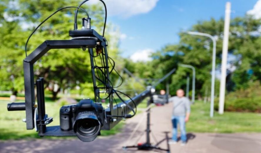
I knew this production would test our planning from the moment I entered the empty venue. The ceiling seemed impossibly distant, the floor was divided among several production departments, and every potential cable route crossed an area that would eventually contain performers, technicians, or equipment. In this case study of a cable cam installation across a large venue, I explain how our crew transformed that complicated space into a controlled aerial filming environment.
The goal was to create smooth, sweeping shots that could travel from one side of the venue to the other. Achieving those movements required more than attaching a camera to a cable. We had to study the structure, calculate the working loads, control cable sag, protect people below the system, and integrate the camera with the wider production workflow.
Understanding the Production Challenge
The creative team wanted continuous shots that revealed the scale of the venue before descending toward the action. A crane could not cover the required distance, while a floor-mounted dolly would have encountered stages, barriers, cables, and moving crew members.
A drone appeared flexible, but it introduced rotor noise, limited operating time, airflow, and safety concerns around people. A cable-suspended camera offered repeatable movement without occupying valuable floor space.
The venue itself created several challenges. Its usable structural points were not perfectly aligned with the desired camera path. Lighting trusses occupied part of the overhead space, and the planned performance area continued to change during pre-production. The camera route therefore had to remain useful without interfering with lighting, sound, staging, or emergency access.
Surveying the Venue Before Rigging
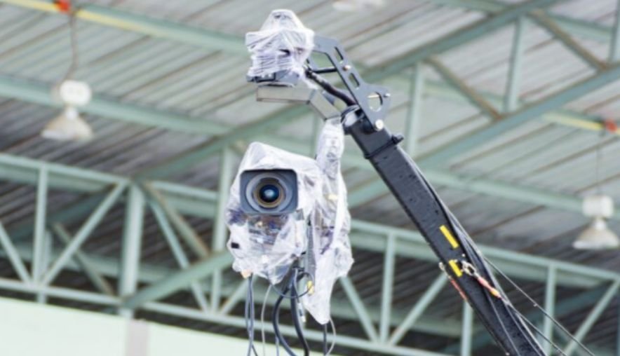
Our installation began with a detailed venue survey. We measured the intended span, examined the available structural elements, documented access restrictions, and identified everything that could enter the camera’s operating envelope.
Mapping the Camera Movement
We marked the desired starting point, endpoint, minimum operating height, maximum height, and safe stopping areas. This helped us separate the creative request from the physical limits of the venue.
Instead of treating the cable as a perfectly straight line, we allowed for sag, payload movement, acceleration, braking, and changes in tension. We also checked whether scenic elements or lighting fixtures would be added after the initial survey.
Reviewing Potential Anchor Points
A structural specialist reviewed the proposed attachment locations before installation. Each point had to withstand forces in the direction created by the tensioned cable, not merely support a downward load.
We documented the approved connections, hardware ratings, load paths, and restrictions. Unrated handrails, decorative beams, temporary fixtures, and unverified roof components were excluded, regardless of how strong they appeared.
Selecting the Cable Cam Configuration
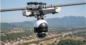
We chose a point-to-point arrangement because the production needed fast movement along one dominant route. A multidirectional system would have increased coverage, but it would also have required additional winches, anchor points, programming, setup time, and operating space.
The selected camera carriage could support the camera, lens, stabilized head, control components, transmission equipment, and safety attachments. We calculated the complete suspended weight rather than relying only on the camera body’s published weight.
The stabilized head gave the camera operator independent control of framing while the cable-cam pilot controlled travel. Separating these responsibilities allowed the pilot to concentrate on speed, clearance, stopping distance, and the movement envelope.
Calculating Tension, Sag, and Working Loads
Cable tension was one of the most important engineering considerations. Increasing tension reduced visible sag, but it also increased the force transferred to the anchors and terminal hardware. Pulling the line tighter was not automatically safer.
Our calculations considered the span, cable weight, suspended payload, intended sag, operating speed, acceleration, braking forces, and an appropriate safety factor. Every connector, sling, termination, pulley, winch component, and anchor had to remain within its approved working load.
Dynamic movement received particular attention. The greatest forces did not necessarily occur while the camera was stationary. Acceleration, abrupt braking, carriage movement, or an emergency stop could create loads higher than the static suspended weight.
Rigging the Cable Camera System
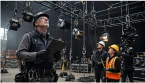
We created a written installation sequence before lifting any equipment. The sequence covered access, anchor preparation, winch placement, cable deployment, carriage connection, secondary retention, communications, inspection, and testing.
The crew established a controlled area below the work zone. Only essential personnel entered while hardware was being installed overhead. Tools and removable components were tethered where necessary, and loose equipment was kept away from edges.
Once the primary cable was in place, we installed the carriage and its independent safety provisions. The crew then checked terminations, fasteners, locking mechanisms, cable alignment, and possible abrasion points. No component was accepted simply because it had been used successfully on an earlier production.
Integrating Camera and Production Control
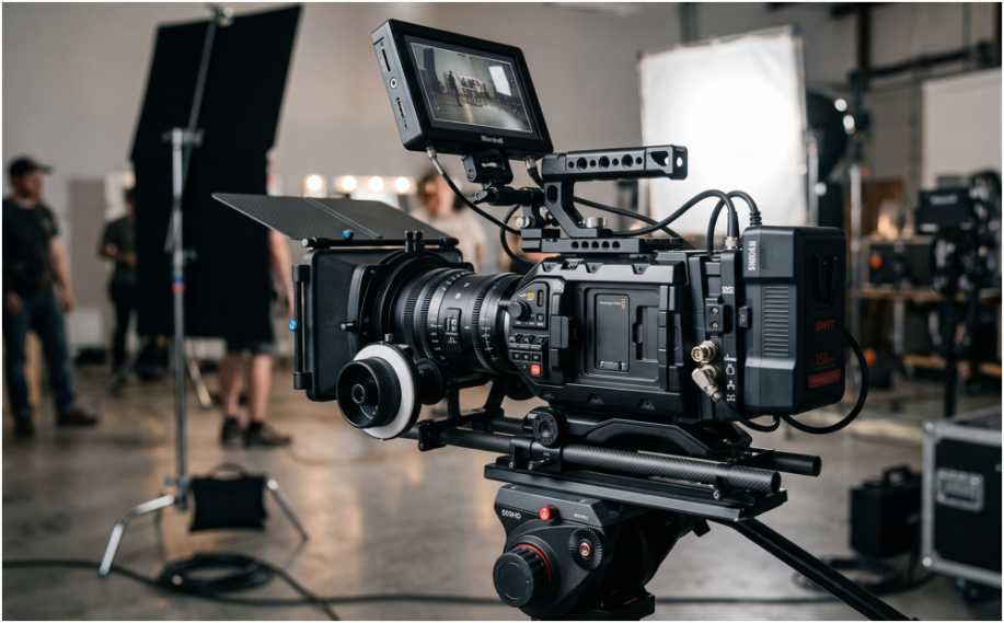
The camera system needed dependable video transmission and remote control throughout the complete span. Because the production team planned to use 35mm film camera equipment for selected shots, we also verified payload compatibility and the required control workflow. We tested the live picture, monitoring delay, lens control, focus response, exposure adjustment, stabilization, communications, and power endurance.
The pilot, camera operator, director, and safety lead used clearly defined communication terms. Commands for movement, rehearsal, stopping, and emergency action could not sound similar. Only one designated person could authorize movement during final testing.
The same communication discipline is essential when coordinating multiple camera operators during a live event, particularly when aerial and ground-based cameras must work together without duplicating coverage or creating conflicting movements.
We also programmed controlled end limits. These prevented normal operating commands from sending the carriage beyond its approved route. Physical clearance and operator judgment remained essential because software limits were only one part of the overall protection system.
Testing the Installation
Testing began without the complete camera payload. We first checked cable tracking, winch response, braking, end limits, unusual vibration, and communication reliability at low speed.
After attaching the operating payload, we repeated the process gradually. The camera travelled through its intended route at reduced speed before progressing to production speed. We checked clearances at the lowest points of the line and observed how the carriage behaved during acceleration and deceleration.
Emergency-stop procedures were rehearsed before creative shots were attempted. The team also established a response plan for power loss, control failure, unexpected obstruction, abnormal cable behaviour, and changes in venue conditions.
Solving an Unexpected Clearance Problem
During rehearsal, a newly repositioned lighting element reduced the available clearance near the middle of the span. The camera could still pass it, but the margin was smaller than the approved operating allowance. Much like rehearsing a presentation, testing the complete production setup revealed a problem that might otherwise have remained hidden until the live event.
We stopped testing and revised the arrangement. Moving the lighting element provided a safer and cleaner solution than increasing cable tension or restricting the camera to an impractical height. The incident demonstrated why a cable-cam system must be checked after other departments complete their overhead work.
Results and Lessons Learned
The completed installation provided smooth wide shots, controlled descents, and repeatable tracking movements across the venue. It avoided consuming floor space and reduced the need to reposition conventional camera-support equipment between production segments.
The most important lesson was that creative planning and rigging planning must develop together. Early structural review prevented unsuitable anchor choices, while movement mapping identified conflicts before installation. Gradual testing exposed a clearance change that might have been missed during a rushed rehearsal.
Frequently Asked Questions
1. What does a large-venue cable cam installation involve?
A case study of a cable cam installation across a large venue normally covers the site survey, structural review, anchor selection, load calculations, rigging, camera integration, exclusion zones, testing, operation, and removal.
2. How long does installation take?
The schedule depends on venue access, system configuration, span, anchor preparation, access equipment, crew size, and testing requirements. Installation should never be shortened by eliminating inspections or rehearsals.
3. Can a cable cam operate above people?
Operation above occupied areas requires professional engineering, approved equipment, risk controls, secondary safety measures, defined operating limits, qualified personnel, and compliance with applicable venue and local requirements.
4. Is a cable cam better than a drone?
A cable cam provides repeatable movement, long operating periods, and controlled indoor travel. A drone offers greater freedom but may introduce noise, airflow, endurance, regulatory, and crowd-safety limitations.
5. Why is cable sag important?
Sag affects camera height, anchor forces, clearance, stability, and the usable movement envelope. Reducing sag by adding tension can substantially increase forces throughout the system.
What the Installation Ultimately Proved
I left the venue convinced that the best aerial shots begin long before the camera moves. They begin with careful measurements, verified structures, realistic load calculations, coordinated departments, controlled testing, and a crew willing to stop when conditions change.
This project succeeded because we treated the system as an engineered installation rather than an isolated piece of camera equipment. For me, that is the defining lesson from this case study of a cable cam installation across a large venue: memorable movement is only valuable when every part of it is planned, tested, and operated responsibly.