



A broadcast camera operator once calculated that capturing a stadium crowd’s collective pulse from the ground requires five stationary camera positions, three operators dodging stage monitor wedges, and constant compromise.
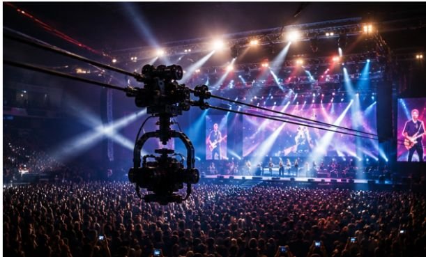
Suspend that same camera on a high-tensile line above the crowd, and a single cable camera system for concert venues captures sweeping, three-dimensional perspectives that make home audiences feel the bass reverberating through the floor.
Modern live music production relies heavily on these aerial rigs. From multi-axis robotic platforms flying over sold-out arena tours to lightweight line-cams operating in mid-sized amphitheaters, aerial tracking shots have evolved from an expensive luxury reserved for the Super Bowl halftime show into a standard line item for high-end touring visuals and live concert films.
The Physics and Evolution of Live Overhead Tracking
When flying a motorized payload directly over thousands of packed concertgoers, safety and physics dictate every single design choice. Traditional jib arms and cranes offer vertical reach, but their fixed fulcrums create a wide, physical footprint on the venue floor and limit movement to a single arc.
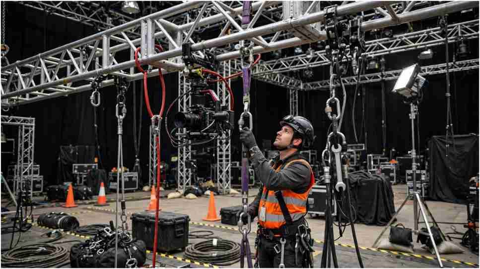
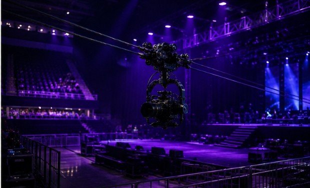
A cable-suspended camera system solves this by using the existing structural architecture of the venue—typically the roof trusses or structural steel—to suspend high-strength lines high above the audience.
+———————————————————————–+
| VENUE ROOF TRUSS STRUCTURE |
| |
| [Winch A]===========\ /===========[Winch B] |
| \ / |
| \ Synthetic Line / |
| \ / |
| \ +——-+ / |
| \–| Gimbal|–/ |
| | Camera| |
| +——-+ |
| / \ |
| / Synthetic Line / |
| / \ |
| [Winch C]===========/ \===========[Winch D] |
| |
| AUDIENCE / STAGE AREA |
+———————————————————————–+
Editor’s Note: A vector-based block diagram illustrating 4-point active winch geometry vs 2-point static line tension would work well here as a visual breakdown for technical readers.
The engineering breaks down into two core mechanical approaches:
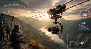
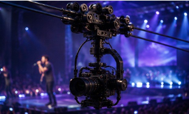
- 2-Point (Point-to-Point) Line Cams: A synthetic or steel line is tensioned between two fixed anchor points (e.g., sound booth to stage header). A motorized trolley travels back and forth along the cable while a gyro-stabilized gimbal controls pan, tilt, and roll.
- 3D Multi-Axis Systems: Four computer-controlled winches are rigged to high points in the corners of an arena. By altering cable lengths in real-time using high-speed mechatronics, the system positions the camera rig anywhere within a three-dimensional flight envelope.
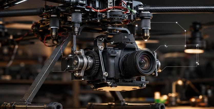
Understanding how cable camera systems work in live events helps production managers appreciate the shift from heavy steel cables to ultra-high-molecular-weight polyethylene lines (such as Dyneema). Synthetics provide higher tensile strength-to-weight ratios, eliminating dangerous line sag while keeping the overall payload lighter.
Market Landscape: From Heavyweight Broadcast to Modular Rigs
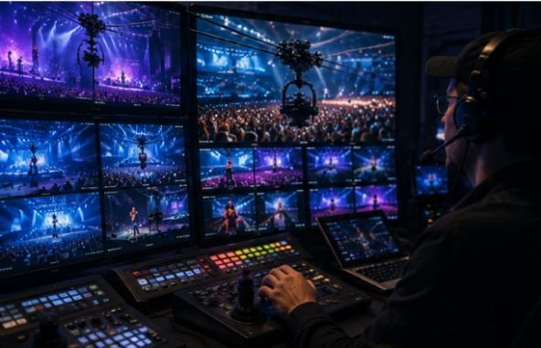
Not every concert venue or tour requires a massive multi-axis setup. The market split between heavy broadcast infrastructure and lightweight portable systems allows teams to select gear based on payload requirements, rigging setup time, and venue capacity.
| System Tier | Key Models | Max Payload | Ideal Venue Type | Primary Strengths |
| Broadcast 3D & Heavy Duty | Ross Video Spidercam, Robycam, Defy Cadence | 30–40+ lbs | Arenas, Stadiums, Large Outdoor Festivals | Full cinema payloads (ARRI, RED), 3D spatial motion, fiber-optic telemetry |
| Mid-Range & Modular | Greenbull FM6 MAX | 13–15 lbs | Mid-Sized Theaters, Amphitheaters, Large Clubs | Gimbal integration (DJI SDK protocol), fast rigging times, high portability |
| Lightweight & Action | Wiral LITE | 3.3 lbs | Intimate Venues, Club Stages, Mobile Shoots | Extremely fast set-up, lightweight anchors, minimal risk profile |
Systems like the Ross Video Spidercam and Robycam rely on heavy mechatronic winches, fiber-optic data transmission, and active gyro stabilization to deliver fluid motion without latency.
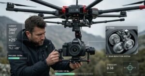
High-payload 2-point rigs, such as the Defy Cadence, carry full cinema packages over spans reaching up to 1,200 feet. Meanwhile, systems integrating open control protocols (like DJI’s RS SDK) let operators use familiar gimbal controllers while lowering gear overhead.
Rigging, RF Congestion, and Redundancy Protocols
Flying heavy equipment over an active crowd requires strict adherence to safety standards and technical coordination. Rigging a camera line is never done in isolation.
+——————————————————-+
| CRITICAL RIGGING PRE-FLIGHT CHECK |
+——————————————————-+
|
v
+——————————————————-+
| 1. Structural Engineering Sign-off & Load Calculations|
+——————————————————-+
|
v
+——————————————————-+
| 2. Clear Lines of Sight & Flying PA Array Offsets |
+——————————————————-+
|
v
+——————————————————-+
| 3. Secondary Mechanical Safety Line & Hard-Stops |
+——————————————————-+
|
v
+——————————————————-+
| 4. Dedicated Spectrum Scan (Fiber vs. Shielded RF) |
+——————————————————-+
1. Rigging Coordination and Structural Loads
Every anchor point must be calculated and approved by the venue’s head rigger. Tensioned cables exert horizontal forces on roof trusses that far exceed the vertical deadweight of the camera itself.
Rigs must clear flying PA speaker arrays, lighting trusses, and moving stage elements. Proper rigging requires following established procedures, such as those detailed in this cable camera anchor point installation guide, to avoid structural overloads.
2. Multi-Tiered Safety Redundancies
When a camera hangs directly over audience members, single points of failure are unacceptable. Professional systems mandate:
- Secondary safety drop-lines attached to independent truss points.
- Autonomous mechanical hard-stops on lines to prevent trolley overruns.
- Dual-power feeds with battery back-ups on winches to ensure control during main stage power dropouts.
3. Surviving Heavy RF Congestion
Concert halls are notoriously hostile radio frequency environments. Thousands of audience smartphones, local production comms, and wireless microphone systems saturate standard 2.4 GHz and 5 GHz bands.
A dropped control packet can cause choppy movement or lost video feeds. High-end systems bypass wireless congestion entirely using fiber-optic lines woven into the support cable. Portable setups rely on directional, frequency-hopping transmitter protocols to maintain line-of-sight signal integrity.
Practical Checklist: Venue Suitability Assessment
Before specifying an overhead system for a live show, production leads should run through this quick operational checklist:
- Structural Point Rating: Are the anchor trusses rated for the horizontal vector loads generated by cable tension?
- Clearance Envelope: Is there a guaranteed 10-foot safety buffer between the lowest point of the camera rig and the highest arm reach of audience members?
- RF Environment Scan: Has a spectrum analyzer confirmed clean channels for wireless video and telemetry (or is fiber available)?
- Sightline Conflicts: Does the cable trajectory cut across primary projection paths, laser rigs, or spotlight angles?
- Emergency Drop Zone: Is there an accessible landing area out of view of the crowd where the crew can service or pull down the rig during a show emergency?
If a venue fails on structural point ratings or safety buffers, production crews should pivot to alternative movement strategies, using tips on how to get smooth handheld shots or stabilized floor gimbals to keep shots steady from the ground.
Limitations and Operational Trade-Offs
Overhead cable cameras are powerful, but they are not universal solutions for every live music setup.
- Rigging Time & Cost: Large 3D setups require dedicated rigging calls, structural load recalculations, and hours of calibration. Smaller venue budgets may be entirely consumed by line-item rigging fees.
- Permitting and Insurance: Local authorities having jurisdiction (AHJ) and insurance underwriters frequently enforce strict guidelines on suspended loads over crowds.
- Sightline Obstructions: While the camera captures impressive visuals for the broadcast cut, the physical cables and trolley can distract audience members in upper-tier seats or obscure stage lights.
Frequently Asked Questions
1. What safety precautions are required when flying a cable camera over a concert crowd?
Operators require dual safety lines, structural rigger approval for anchor points, mechanical hard-stops, and redundant power systems to prevent hardware failures over audience areas.
2. How do cable camera systems avoid signal interference from concert RF noise?
Professional rigs use optical fiber woven directly into the synthetic line. Portable rigs use specialized, high-frequency transmitters with frequency-hopping protocols to bypass venue RF chatter.
3. What is the main mechanical difference between a 2-point and a 3D cable camera?
A 2-point system travels along a single line between two fixed anchors. A 3D system uses four computer-controlled winches to adjust line lengths, moving the camera anywhere within a 3D space.
4. Can mid-sized venues support a cable camera system?
Yes. Mid-sized venues frequently use lightweight 2-point cable systems or modular carbon fiber rigs paired with mirrorless cameras to keep line tension low and setup fast.
The Operational Reality
A cable camera system turns a standard venue into a dynamic studio space. By balancing load physics, redundant safety systems, and clean frequency management, operators can deliver cinematic live concert visuals that pull home viewers straight onto the stage.