



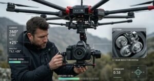
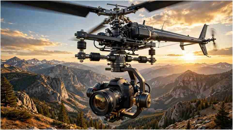
The VR360 solved a difficult photography problem before stabilized camera drones became common. It let photographers capture complete spherical panoramas from an RC helicopter without building a custom rotating mount.
I examined the original product information to understand what made this equipment useful. Its clever value was not rotation alone. The system addressed camera alignment, vibration, aircraft movement, landing protection and payload balance within one modular mount.
What Is the VR360 Camera Mount?
The VR360 Carbon V2 was an aerial camera mount developed by PhotoShip One. It attached beneath an electric RC helicopter and rotated a camera around a vertical pan axis.
Photographers used the mount to capture overlapping photographs in every horizontal direction. Stitching those frames produced an immersive spherical scene rather than one conventional aerial image.
This distinction matters. The system was not a virtual-reality headset or a modern 360 action camera. It was mechanical equipment designed to position and rotate a separate DSLR during flight.
The mount also supported oblique photography. Its included conversion kit replaced the panorama gimbal with a roll-and-pitch leveling unit. According to the original description, the conversion required loosening three screws and took about 20 seconds.
How Does the Aerial Panorama System Work?
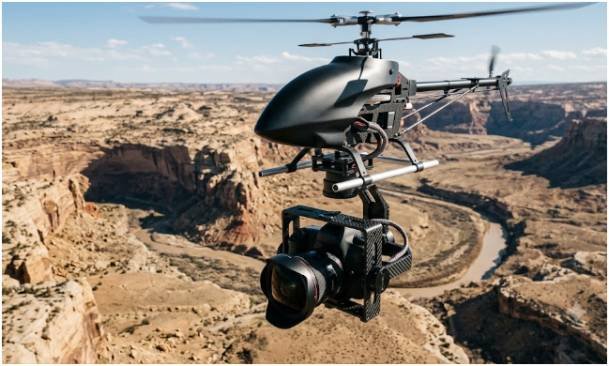
Creating an aerial panorama involves more than turning the camera through one circle. Every frame needs sufficient overlap, stable exposure and a reasonably consistent horizon.
The original workflow used six to eight portrait-orientation photographs. A fisheye lens provided a wide field of view, reducing the number of frames needed to cover the scene.
Capturing the source photographs
The operator rotated the VR360 to a series of planned positions and triggered the camera at each stop. Consistent yaw intervals made the sequence easier to assemble later.
Seven evenly spaced positions, for example, place each capture about 51.4 degrees apart because 360÷7=51.4360 \div 7 = 51.4. That figure describes camera spacing, not guaranteed image overlap. Actual overlap depends on the lens, sensor, orientation and usable field of view.
The camera’s entrance pupil should sit close to the rotation axis. Poor alignment creates parallax, where foreground and background objects shift relative to each other. Those shifts can cause broken lines and stitching errors.
Stitching an equirectangular panorama
The captured images are imported into panorama software. The program finds matching details, aligns the frames and blends them into an equirectangular image.
The original page recommended PTGui for stitching. It also referenced Pano2VR for converting the final image into an interactive presentation. Flash and QuickTime VR were common delivery formats then, but modern output should use HTML5-compatible viewers.
Exposure consistency remains essential. Manual exposure, fixed white balance and locked focus can prevent visible changes between adjoining frames. Moving trees, water, vehicles and people may still create seams because they change position during the sequence.
Which Engineering Features Made It Different?
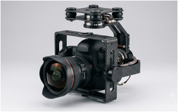
The mount combined carbon construction with an interlocking modular design. That approach sought to limit weight without sacrificing the stiffness needed around the camera and pan mechanism.
Its most valuable features addressed problems that ordinary camera brackets could not solve reliably in flight.
Adjustable camera positioning
The four-axis gimbal allowed adjustment along the x, y and z directions, plus pan. These controls helped the operator position the lens correctly and balance the camera assembly.
Balance affects both image quality and component life. A poorly balanced camera forces the servo to work harder. It can also increase vibration and make the horizon less predictable.
The adjustable bracket also accommodated different camera bodies and lenses. However, mechanical fit does not automatically confirm safe payload capacity or ideal balance.
Roll damping and pan protection
The roll axis used an adjustable oil damper. The camera could reportedly self-level by approximately 15 degrees on either side of center.
This system could reduce gentle aircraft roll, but it should not be confused with a modern electronic three-axis stabilizer. Sudden movement could still affect image alignment.
A 100 oz-in pan servo powered rotation. An integrated pan-lock held the mount in place while the helicopter was on the ground. That feature protected the servo from torque generated during rotor spool-up.
Which Cameras and Helicopters Can Use It?
The original compatibility list included Nikon D40, D40X and D60-series cameras. It also mentioned Canon 30D and 40D bodies paired with 8 mm or 10 mm fisheye lenses.
Supported helicopter platforms included the T-Rex 600, T-Rex 700, Logo 500 and 600, Maxi-Joker 2 and 3, and Raptor E620. These are historical compatibility references, not confirmation that every altered or rebuilt aircraft remains suitable. You should consider the types of camera movements before reaching to a conclusion.
Before using legacy equipment, I would inspect the carbon plates, bearings, servo gears, fasteners and vibration isolators. Material damage or unavailable replacement parts can make an apparently compatible setup unsafe.
How Is the Camera Mount Installed?
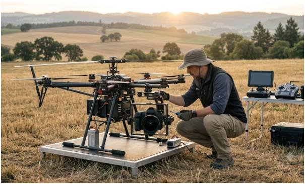
PhotoShip One described two installation methods. The correct choice depended on the helicopter frame and whether the operator wanted to retain its landing skids.
Helicopter-specific adapter plates
Vertical G10 plates bolted directly to supported helicopter side frames. Four Lord vibration isolators separated the aircraft from the photography assembly.
This configuration required removing the standard landing skids. The necessary adapter plates were not included with the basic VR360 package, so buyers had to obtain the correct model-specific hardware separately.
Universal Astro mounting system
The Astro mount provided a broader compatibility option. The helicopter sat above the photography platform with its landing skids still installed.
Operators secured the skids using O-rings or bungee straps. Multiple mounting holes accommodated different skid lengths and helped adjust the combined center of gravity.
A universal bracket still demands careful testing and battery system like V-Mount Batteries. Secure attachment, level balance and adequate clearance must be confirmed before the rotor starts.
What Are the Main VR360 Technical Specifications?
The 2.0 mm carbon version was intended for 680–830-class electric helicopters with a stated maximum helicopter weight of 20 pounds.
The original specifications listed a width of 475 mm at the skids, a height of 310 mm and a mount weight of 822 grams, or roughly 1.8 pounds. Other features included continuous pan rotation, a one-way bearing, an adjustable gear ratio and a hollow 10 mm pan shaft.
Payload planning must include more than the camera. Consider this worked example:
- Camera and lens: 750 grams
- Camera mount: 822 grams
- Adapter and attachment hardware: 150 grams
- Combined added load: 1,722 grams, or about 3.8 pounds
That calculation excludes wiring, receivers and other accessories. Operators must check the aircraft manufacturer’s limits and measure the completed takeoff weight.
What Should Operators Check Before Flying?
A legacy aerial mount should undergo a restrained ground test before any flight. I would first test pan movement without rotor power. I would then inspect balance, fastener security, servo temperature, vibration isolation and camera clearance.
US operators must also determine which FAA rules govern the flight. Recreational pilots generally must keep the aircraft within visual line of sight, take TRUST and comply with registration requirements. Commercial or other non-recreational photography normally falls under Part 107.
Registered aircraft generally need to comply with Remote ID requirements. Controlled airspace may also require authorization. Operators should verify current rules and local restrictions before each flight rather than relying on historical product documentation.
Does the System Still Make Sense Today?
Modern drones offer electronic stabilization, automated waypoint control and integrated panoramic modes. They are usually easier to transport and operate than large RC helicopters carrying DSLR equipment.
Even so, the VR360 remains relevant as an engineering case study. It shows how designers handled aerial panoramas when cameras, aircraft and rotation systems were separate components.
A surviving unit may appeal to collectors, experimental photographers or operators maintaining older equipment. Its current availability, support status and replacement-part supply should be confirmed before purchase or flight.
Frequently Asked Questions
1. What was the VR360 camera mount used for?
It rotated a DSLR beneath an RC helicopter to capture overlapping photographs for aerial spherical panoramas.
2. How many photos are needed for a 360-degree aerial panorama?
The original workflow used six to eight portrait frames, although the ideal count depends on the lens, sensor and required overlap.
3. Can modern panorama software process its photographs?
Yes. Current stitching software can process suitable overlapping images and export equirectangular files for HTML5 panorama viewers.
4. Can I attach the mount to any RC helicopter?
No. Frame strength, payload capacity, balance, attachment hardware and aircraft dimensions must all be verified before installation.
The Final Spin: Know the Hardware Before Takeoff
The VR360 was more than a rotating camera bracket. Its adjustable gimbal, oil damping, servo protection and mounting options addressed real challenges in early aerial panorama photography.
My practical advice is simple: treat surviving equipment as a legacy system, not a ready-to-fly accessory. Inspect every component, calculate the complete payload and confirm current FAA requirements before the rotor turns.