



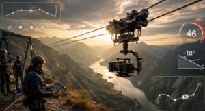
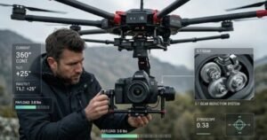
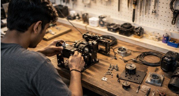
Hollywood productions drop tens of thousands of dollars on high-tension cable cam rigs to pull off buttery-smooth, dynamic sweeping shots over stadiums and dense forests. Yet, with off-the-shelf Radio Control (RC) parts, basic metalworking tools, and a weekend in the garage, you can build a diy motorized cable cam kit that delivers 90% of that cinematic punch for a fraction of the price.
The secret isn’t expensive custom fabrication; it’s mastering mechanical leverage, friction drive mechanics, and electronic speed management. Whether you are filming high-speed mountain biking, low-budget indie features, or outdoor athletics, taking your camera off the ground unlocks spatial visual angles that no drone or gimbal can achieve in tight canopy conditions.
The Physics of Motion: Why Cable Cams Outperform Drones in Dense Spaces
Drones revolutionized aerial cinematography, but they come with massive operational liabilities: battery draw measured in minutes, severe noise pollution, FAA compliance headaches, and an inherent risk of flying near tree branches or crowds.
A cable camera system eliminates those restrictions, giving you repeatable, pinpoint-accurate tracking passes through spaces where multirotors simply cannot fly.
+————————————————————-+
| TENSIONED STATIC LINE |
+————————————————————-+
|
+————–+
| TROLLEY RIG |
| [ESC + RC] |
+————–+
|
+————–+
| GIMBAL MOUNT |
+————–+
|
[CAMERA SYSTEM]
Editor’s Note: A simple structural line diagram showing the relationship between tensioned cable, trolley housing, stabilized gimbal, and camera platform works best to visualize the weight distribution here.
According to mechanical engineering studies published by institutions like the American Society of Mechanical Engineers (ASME), friction coefficients between drive wheels and synthetic lines drop dramatically when line sag exceeds 5 degrees. This means the performance of your rig relies heavily on how well you manage mechanical tension and weight distribution.
Deconstructing the System: Essential Parts and Hardware
To build a reliable DIY motorized cable cam kit, you need to combine structural mechanics with hobby-grade RC electronics. Instead of buying proprietary kits, you can source high-spec components directly.
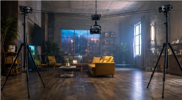
1. Trolley Frame and Wheel Architecture
The chassis houses the weight load and must remain light enough to avoid unnecessary line sag.
- Frame: Lightweight CNC-milled 6061-T6 aluminum plates or structural carbon fiber sheet provide the best strength-to-weight ratio.
- Sheaves/Wheels: U-groove polyurethane wheels or patio door rollers fitted with high-ABEC rated skateboard bearings ensure smooth tracking across the line.
2. Drivetrain and Power Delivery
- Motor: A high-torque brushless RC car motor (around 800KV to 1200KV) or a geared DC motor provides continuous torque at low RPMs.
- ESC (Electronic Speed Controller): A heavy-duty, sensor-based ESC gives you precise throttle control, allowing for slow creeps as well as fast speed runs.
- Power Source: A 3S or 4S Lithium Polymer (LiPo) battery pack delivers the high discharge rates needed to move heavy payloads up inclines.
3. Line, Rigging, and Stabilization
- Line Material: 5mm UHMWPE (Dyneema/Spectra) static line is preferred over steel aircraft cable because it offers high tensile strength with negligible weight.
- Damping: A rubber vibration isolator placed between the trolley chassis and your motorized gimbal stops high-frequency motor vibrations from reaching the camera sensor.
| Component | Standard DIY Option | Professional Upgrade | Primary Function |
| Main Line | 1/4″ Static Paracord | 5mm UHMWPE (Dyneema) | Supports payload without stretching |
| Drive Motor | Brushless RC Motor | Geared DC Servo Motor | Provides high-torque propulsion |
| Chassis Material | Marine Plywood / Acrylic | 6061-T6 Aluminum / Carbon Fiber | Rigid structural body |
| Control System | 2.4GHz RC Transmitter | Custom Telemetry Controller | Precise throttle and braking |
Step-by-Step Blueprint: Building and Wiring Your Rig
Assembly requires precision. Misaligned pulleys cause rapid wheel wear and inconsistent speed output.
Step 1: Fabricate the Chassis
Cut twin matching side plates out of aluminum or thick composite material. Bore precision holes for the top drive wheel, lower guide pulleys, and gimbal mounting plate. Ensure the center of gravity aligns directly underneath the drive wheel.
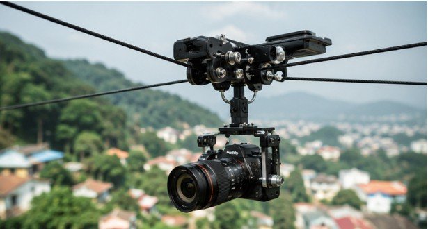
Step 2: Configure the Friction Drive
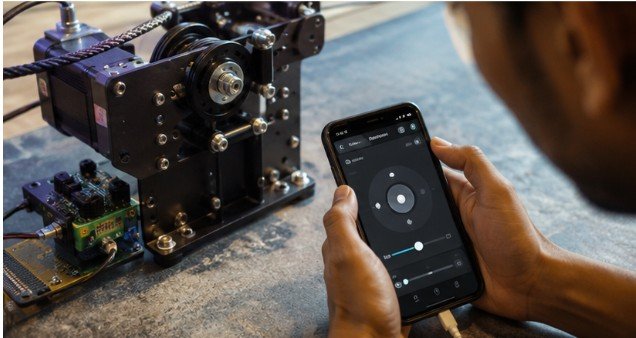
Mount your brushless motor to an adjustable sliding plate. Your drive wheel needs to press firmly against the tensioned cable, sandwiching the line between counter-bearing pinch rollers. This friction-fit design prevents slippage when accelerating or braking uphill.
+————————————+
| TOP DRIVE WHEEL |
+————————————+
====================================== <– CABLE / LINE
+————————————+
| COUNTER PINCH ROLLER |
+————————————+
Step 3: Wire the Control Electronics
Connect your motor leads to the sensor-based ESC. Plug the ESC signal wire into channel 1 of your 2.4GHz RC receiver, and attach your 3S/4S LiPo battery through a high-current connector like an XT60 or EC5. Calibrate the neutral throttle point on your RC transmitter before attaching any camera equipment.
Rigging, Tensioning, and Field Setup
A poorly tensioned line leads to excessive sag, sluggish motor response, and unsafe operational strain on your anchor points.
Before launching your rig, review this guide on how to set up cable cam rigs to properly prepare your field environment. Calculating line strain is equally critical; check out how to calculate cable cam tension to prevent line failure under dynamic loads.
Pre-Flight Safety Checklist
- [ ] Inspect main line for fraying, dynamic wear, or knot degradation.
- [ ] Check anchor strength (use load-rated tree straps or structural steel columns).
- [ ] Verify motor-to-line contact pressure and drive wheel tension.
- [ ] Test emergency fail-safe braking on your RC transmitter.
- [ ] Secure safety lanyards between the gimbal, camera, and trolley frame.
Limitations and Operational Trade-Offs
If you’re tackling a complex shoot, you might also consider how to hire a cable camera operator for professional support. While DIY motorized cable cams are versatile tools, they do have operational limitations you need to keep in mind:
- Line Sag Physics: No cable can be pulled 100% straight over long distances without breaking. You will always experience a slight parabolic dip in the center of your run.
- Wind Resistance: Crosswinds push against the static line, introducing lateral roll movements that test the limits of your 3-axis gimbal stabilization.
- Thermal Limitations: Long, continuous runs with high payloads heat up RC electronics quickly. Keep an eye on motor temperatures to prevent thermal shutdown mid-run.
Frequently Asked Questions
1. What type of line is best for a DIY cable cam?
5mm UHMWPE (Dyneema) static rope is ideal. It has minimal stretch, an extremely high strength-to-weight ratio, and produces far less wheel wear than steel wire ropes.
2. How do I stop my cable cam from slipping on inclines?
Increase the compression on your friction drive system. Using a dual-wheel pinch mechanism forces the drive pulley against the line, maintaining traction even on steep inclines.
3. How much weight can a DIY motorized cable cam carry?
A well-engineered aluminum trolley with a high-torque brushless motor can easily carry 8 to 15 pounds, which is enough for a DSLR or cinema camera paired with a 3-axis gimbal.
Mastering the DIY motorized cable cam kit comes down to balancing weight, friction, and motor torque. By building your own system, you gain complete control over your rig’s performance, turning challenging locations into dynamic cinematic sets. Build smart, double-check your rigging tension, and enjoy the smooth motion shots you can create.