



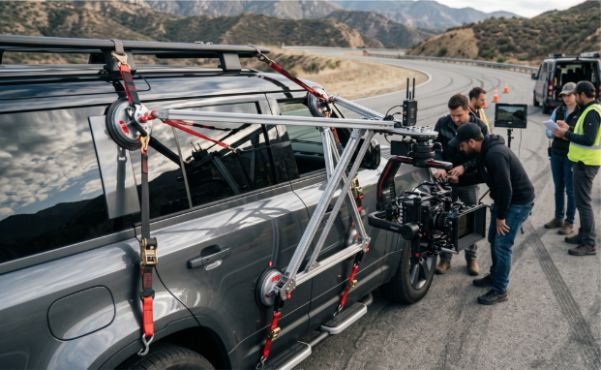
A camera may look secure while the vehicle is parked, then begin twisting once airflow, acceleration, and road vibration enter the equation. This vehicle-mounted camera rigging case study shows how I approached those forces during a controlled exterior car shoot.
The setup used vacuum mounts, aluminum speed rail, a gimbal, and a cable-based vibration isolator. More importantly, it used triangulation, independent retention, gradual testing, and a closed filming route. This was not a suction-cup-and-go installation.
The Shot, Vehicle, and Rigging Requirements
The production needed a low, forward-facing shot from the passenger side of a midsize vehicle. The camera had to remain close to the body while preserving clearance around the front wheel.
The complete payload included the camera body, lens, media, battery, gimbal, mounting plate, cables, and wireless control hardware. I treated that total assembled weight as the payload. Using only the camera body’s published weight would have understated the load.
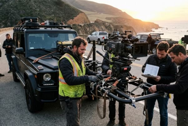
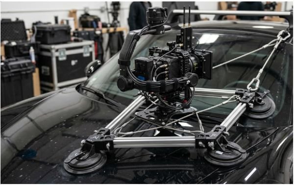
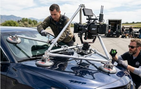
We selected a modular system based on pump-activated vacuum mounts and 1.5-inch aluminum speed rail. A cable-supported vibration isolator sat between the rail structure and gimbal.
Proaim lists an 8-inch Action-King system with a payload rating of up to 100 kilograms. That specification applies to the manufacturer’s complete system and stated operating conditions. It should not be interpreted as permission to place that load on any vehicle panel.
The working load was therefore limited by more than the strongest component. Panel stiffness, clamp orientation, rail span, vehicle speed, road quality, dynamic forces, and secondary retention all affected the practical limit.
Building the Vehicle Camera Mount
Preparing and Mapping the Mounting Surface
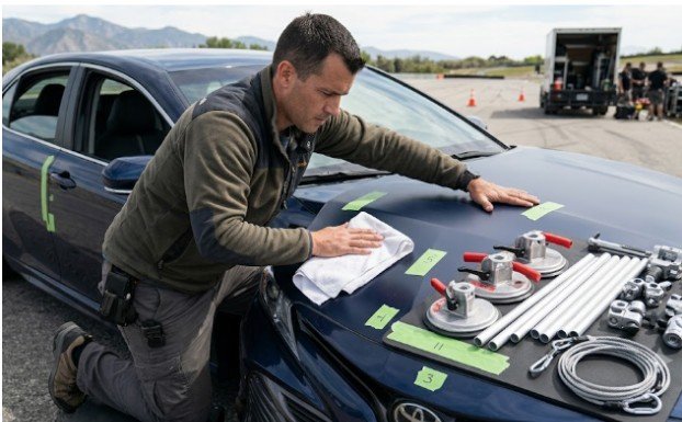
I began by washing and drying every proposed contact area. Fine dust, wax residue, moisture, or panel contamination can compromise a vacuum seal or allow a mount to creep.
Next, I pressed each panel by hand to locate stiff and flexible areas. The center of a wide hood or door skin often flexes more than edges, pillars, or reinforced panel transitions. A cup attached to a flexible section may remain sealed yet still transmit movement into the camera.
The mounting map also accounted for door operation, windshield visibility, wheel clearance, exhaust heat, body seams, and cable routing. Nothing crossed an airbag zone or entered the driver’s view.
This early mapping stage became one of the most valuable lessons from the vehicle-mounted camera rigging case study. A secure component attached to a weak location still produces a weak installation.
Creating a Triangulated Speed-Rail Structure
Three primary vacuum mounts formed the base. Short rail sections connected them into a triangulated framework rather than a flat, rectangular grid.
Triangulation reduced the system’s ability to rack or twist. One rail controlled vertical movement, another resisted lateral movement, and the third helped manage fore-and-aft loads. The camera platform sat near the center of that structure to reduce leverage.
I kept each rail as short as the framing allowed. Long unsupported tubes increase flex and can amplify small movements at the camera.
Every fitting was oriented so the expected force pushed into the connection rather than prying it apart. Clamps, crosses, and swivel fittings were tightened, marked, and rechecked after the initial static load was applied.
A matte box was excluded from this configuration because the shot did not require filters. For builds where lens accessories affect payload, airflow, or rod balance, knowing about clamp-on vs rod-mounted matte box helps determine which arrangement creates fewer mounting complications.
Adding Vibration Isolation
Structural stiffness and vibration isolation perform different jobs. The rail grid prevents large movement, while the isolator reduces higher-frequency energy reaching the gimbal.
We used a modular cable-based isolation platform between the speed rail and camera gimbal. RigWheels describes its Cloud Mount as an adjustable vibration-isolation system designed to help handheld gimbals operate more effectively on moving platforms.
Isolation must match the payload. A system tuned for a heavier cinema package may barely move under a mirrorless camera. A soft configuration can also create slow oscillation during braking or cornering.
I adjusted the cable geometry with the complete camera package installed. The final setting allowed controlled movement without letting the gimbal strike the surrounding frame.
Vehicle Camera Rig Safety and Redundancy
Independent Tethers and Secondary Restraints
The primary structure never served as its own backup. The camera cage received an independent rated tether connected to a separate vehicle attachment point.
A second restraint limited how far the main rig could travel if a primary mount shifted. Its routing avoided sharp panel edges and hot components. It also remained short enough to prevent the detached assembly from striking a wheel, window, or occupant.
Ratchet straps were used only where their direction improved the structure. Excessive tension can deform bodywork, overload fittings, or pull vacuum cups sideways. Each strap had a defined purpose rather than serving as a visual sign of safety.
The vehicle-mounted camera rigging case study reinforced a simple rule: redundancy must survive the same failure that defeats the primary system. A tether connected to the failed rail grid is not independent redundancy.
Managing the Vehicle and Filming Environment
The rig was tested on a controlled route with restricted access. The driver, camera team, and safety lead agreed on speed limits, stop commands, communication channels, and emergency procedures before movement began.
OSHA identifies transportation incidents as a major cause of occupational fatalities and recommends formal driver-safety policies, training, and workplace vehicle controls.
Those principles matter even when no single OSHA rule describes a specific cinema car mount. Producers should also check state traffic laws, permit conditions, insurance requirements, and local film-office rules.
Exterior rigs should not be improvised on active public roads. A qualified key grip, vehicle-rigging specialist, stunt coordinator, or engineer may be required, depending on the speed, payload, mounting method, and shooting environment.
Camera Settings for Reducing Road Vibration
The first camera test used normal stabilization settings. It produced an unexpected result: the footage showed small edge distortions even though the gimbal appeared stable.
For this camera and lens combination, disabling in-body and optical stabilization produced a cleaner frame. The mechanical isolator and gimbal were already correcting motion, while the internal stabilization system appeared to react to residual high-frequency vibration.
That finding is not universal. Some cameras perform better with stabilization enabled. I recommend recording identical short tests with stabilization on and off before choosing a setting.
We also tested a 90-degree shutter angle. The shorter exposure reduced blur during sharp impacts and gave post-production tracking a clearer frame. However, it created a more staccato look than a conventional 180-degree shutter.
The final decision depended on the shot. For fast road texture and aggressive movement, the 90-degree setting worked. For a softer commercial look, slower vehicle movement and a wider shutter angle would have been preferable.
The Staged Testing Process
The team never moved directly from installation to production speed. The testing sequence progressed through five controlled stages.
First, we performed a parked inspection with the full payload installed. We checked vacuum indicators, fittings, rail clearances, gimbal travel, tether routing, monitoring, and emergency access.
Second, the vehicle moved at walking speed. After stopping, I checked every witness mark and attachment point.
Third, speed increased in small steps. The team reviewed footage after each run for vibration, horizon movement, rolling-shutter distortion, focus consistency, panel flex, and unwanted reflections.
Fourth, the driver repeated planned acceleration, braking, and turns at reduced intensity. These maneuvers revealed loads that a straight, constant-speed test could not reproduce.
Finally, the rig received another complete inspection before the recorded take. Any meaningful change in lens, battery, camera position, road surface, or speed would have restarted the test sequence.
This staged approach was the most transferable method in the vehicle-mounted camera rigging case study. It turned testing into evidence rather than reassurance.
Results and Lessons From the Setup
The first moving test showed a small horizontal twitch on sharp bumps. Tightening the gimbal did not solve it. The cause was a long rail section flexing between two fittings.
We shortened that span and moved one mounting point closer to the camera platform. The next run showed less frame movement without making the isolator excessively stiff.
That result challenged the instinct to solve every vibration problem at the camera. Sometimes the visible shake begins several feet earlier in the load path.
The successful setup relied on five connected controls: a stiff mounting location, triangulated rails, payload-matched isolation, independent restraints, and staged testing. Removing any one of them would have reduced safety or image quality.
Frequently Asked Questions
1. Are suction cups safe for vehicle camera mounting?
Professional vacuum mounts can be suitable when correctly rated, monitored, placed, and backed up, but they should never be the only retention method.
2. How do professionals reduce vibration in car-mounted footage?
They combine a rigid triangulated frame, a payload-matched isolator, a balanced gimbal, short rail spans, and controlled road testing.
3. Should IBIS be turned off on a vehicle camera rig?
Test both settings because some camera systems misread high-frequency road vibration, while others benefit from stabilization.
4. What is the biggest lesson from this vehicle-mounted camera rigging case study?
The strongest component does not determine safety; the entire load path, mounting surface, operating speed, and backup system must work together.
Final Take: Smooth Footage Is Earned Before “Action”
My biggest takeaway from this vehicle-mounted camera rigging case study was that smooth footage begins with structural decisions, not post-production software. A gimbal cannot rescue a flexible rail, and a safety cable cannot justify a careless primary mount.
Map the vehicle, calculate the complete payload, triangulate the structure, isolate the camera, and test one variable at a time. Then inspect the entire system again. The glamorous tracking shot should be the last step, not the first experiment.