





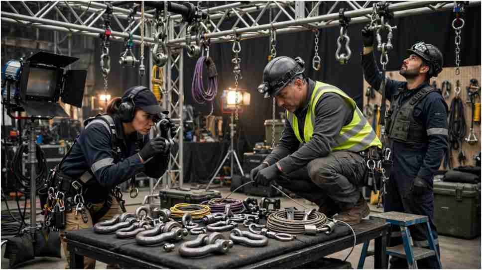
A 2,000-pound shackle does not automatically mean you can hang a 2,000-pound load from it. Change the pull direction, sling angle, hitch, temperature, or connected component, and that usable capacity may change.
That is the point I keep front and center when looking at film rigging hardware load ratings explained correctly: the number stamped onto the hardware is only meaningful within the conditions under which the manufacturer rated it.
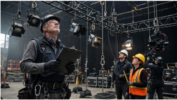
On a film set, that distinction matters because the load may be sitting above a camera package, lighting position, performer, or crew pathway.
The Number That Actually Matters Is the WLL
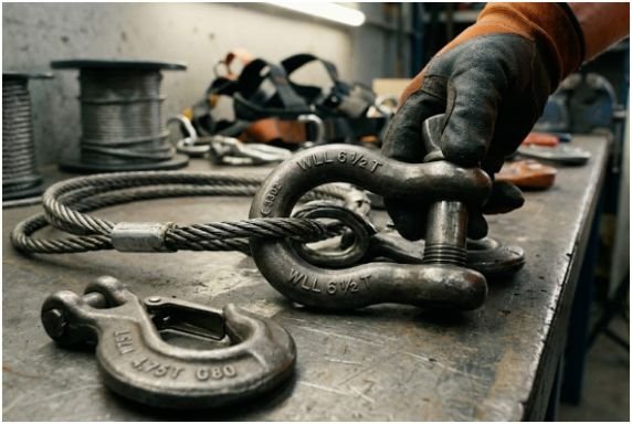
Working Load Limit, or WLL, is the maximum load a manufacturer authorizes for a component under specified operating conditions.
OSHA requires covered wire-rope and alloy-chain slings to stay within the rated capacities shown by their manufacturer identification. It also requires daily inspection of slings and their attachments before use.
WLL, MBS, SWL and Design Factor
These terms sound similar but answer different questions.
| Term | What it tells me | How I use it |
| WLL | Maximum permitted working load under rated conditions | Primary working number |
| MBS/MUS | Approximate minimum load associated with ultimate failure | Not a normal operating limit |
| Design factor | Relationship between ultimate strength and rated capacity | Built into equipment design |
| SWL | Safe-working terminology still found in industry use | Verify exactly how it was established |
The critical distinction is simple: breaking strength is not working capacity.
I never treat an impressive MBS number as permission to create my own WLL.
Why the 5:1 and 10:1 Shortcut Can Mislead You
A common explanation says static film loads use a 5:1 factor while dynamic or higher-risk loads use 10:1.
That is too broad to use as a hardware-selection rule.
Different products can be manufactured around different design factors. The factor may also depend on the applicable standard, product category, intended use, system design, or engineering requirements.
So this calculation:
WLL = breaking strength ÷ assumed safety factor
is useful for understanding the concept, but it should not replace the manufacturer’s marked capacity.
That is one reason film rigging hardware load ratings explained properly starts with the product data rather than a universal ratio.
Entertainment systems also have dedicated ANSI standards. ESTA lists standards covering powered hoists, static suspended systems, chain hoists, and permanent rigging support points. ANSI E1.56 was updated in 2026 for permanent rigging support points.
The Rating Changes When the Rig Changes
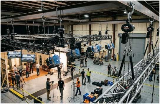
The catalog WLL does not exist independently of configuration.
Shackle Side Loading
Shackles generally perform best when the load travels through their intended centerline.
One Crosby technical document says side loading should be avoided. For the products covered by that document, its reduction chart gives these values:
| Load direction | Remaining WLL |
| 0° inline | 100% |
| 45° side load | 70% |
| 90° side load | 50% |
So a hypothetical shackle with a 2,000-pound WLL would have only 1,400 pounds available at a 45° side load if that exact manufacturer’s reduction table applied.
That last sentence matters. Do not copy those percentages onto another shackle without checking its documentation.
Connection geometry is a major part of shackle and sling safety for film rigging, because a correctly rated component can still be incorrectly loaded.
Sling and Bridle Angles
Two sling legs do not automatically divide a load 50/50.
As the legs move closer to horizontal, their tension rises.
For a symmetrical two-leg bridle:
Leg tension = load ÷ (2 × sin angle from horizontal)
That relationship creates a surprisingly fast increase.
An 800-Pound Load That Becomes Two 800-Pound Leg Loads
Take an evenly distributed 800-pound suspended lighting assembly.
At a 60° sling angle:
800 ÷ (2 × sin 60°) ≈ 462 lb per leg
At 45°:
800 ÷ (2 × sin 45°) ≈ 566 lb per leg
At 30°:
800 ÷ (2 × sin 30°) = 800 lb per leg
| Sling angle from horizontal | Approx. tension per leg |
| 60° | 462 lb |
| 45° | 566 lb |
| 30° | 800 lb |
Nothing was added to the 800-pound fixture. Geometry alone pushed each leg from 462 pounds to 800 pounds.
That is why film set overhead rigging load calculation must include the actual bridle geometry rather than simply dividing total weight by the number of slings.
OSHA likewise requires wire-rope sling identification to state rated capacity for the hitch and the angle on which that capacity is based.
The Weakest Component Sets the Limit
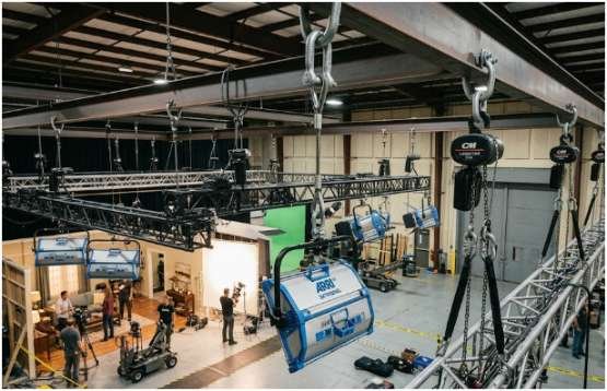
A rig is not rated according to its strongest component.
Imagine a suspended assembly containing:
- 2,000-pound-rated shackles
- a 1,500-pound sling
- a 1,000-pound rated connection
- an 800-pound rated attachment point
Ignoring other necessary derating and engineering considerations, that 2,000-pound shackle does not turn the assembly into a 2,000-pound system.
The lower-rated component becomes the immediate limiting link.
OSHA applies the same logic to alloy-chain assemblies by requiring hooks, links, and other attachments to have capacity at least equal to the chain.
This weakest-link mindset also supports dropped object prevention on film sets. The visible load is only part of the problem; every attachment between the load and supporting structure needs scrutiny.
Ratings Mean Nothing If the Hardware Is Damaged
A stamped WLL is not a lifetime guarantee.
Damage changes the equation.
OSHA requires covered slings and attachments to be inspected each day before use. Damaged or defective slings must be removed from service. It also prohibits shock loading of wire-rope slings and requires protection where slings contact sharp load edges.
Synthetic web slings carry additional concerns. OSHA specifies identification for rated capacities and sets operating-temperature restrictions for several synthetic materials.
On a working set, I would treat an unreadable tag, distorted shackle body, damaged thread, cut sling, heat exposure, unexplained modification, or questionable attachment as a reason to stop and verify—not as something to “watch for later.”
What I Check Before an Overhead Load Leaves the Ground
For film rigging hardware load ratings explained in practical terms, I reduce the decision to four questions.
First, what does the manufacturer actually rate this specific component for?
Second, does the real installation match that rated configuration?
Third, have angles, side loads, hitches, movement, temperature, dynamic effects, and the complete load path been accounted for?
Fourth, is every component—including the supporting point—rated for the force it will actually experience?
If any answer depends on guessing, I do not treat the load rating as established.
For US productions, OSHA requirements also depend on the work activity and circumstances. Entertainment-specific ANSI/ESTA standards can provide additional system-level requirements, but they do not turn a manufacturer’s WLL into a flexible number.
Frequently Asked Questions
1. What does WLL mean on film rigging hardware?
WLL is the manufacturer’s maximum permitted working load for the hardware under its specified configuration and conditions.
2. Are 5:1 and 10:1 safety factors mandatory for all film rigging?
No. Design factors vary, so use the applicable standard, engineered design, and manufacturer’s rated WLL rather than assuming one universal ratio.
3. Why do sling angles reduce rigging capacity?
Flatter sling angles increase tension in each leg, so the hardware may experience much more force than a simple load division suggests.
4. Why are film rigging hardware load ratings explained differently for side loads?
Because many components are rated primarily for inline loading, and manufacturers may require substantial WLL reductions when loads move off-axis.
The Stamp Wins, Not the Guess
The most dangerous load-rating mistake is rarely forgetting what WLL means. It is believing that one printed number follows the hardware into every possible configuration.
It does not.
Angles change forces. Side loading changes capacity. Dynamic movement adds force. Damaged gear can lose integrity. And one underrated component can dictate the capacity of an otherwise heavy-duty system.
My next move before approving an overhead setup would therefore be simple: trace the complete load path from suspended object to supporting structure and verify every rating against its actual loading condition.
A rigging calculation should prove the setup works. The fact that the hardware “looks strong enough” proves nothing.