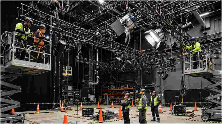





When I check how to calculate safe working load for film rigging, I do not start by dividing a breaking-strength number. I start with the full load path. A camera package can sit below a sling rating while an angled bridle, connector, moving head, or support point becomes the real limit.
OSHA requires slings to carry rated-capacity identification and prohibits loading them beyond their rated capacities. I therefore trust the manufacturer’s working load limit first, not a capacity invented from raw breaking strength.
The Number on the Tag Beats the Number You Invent
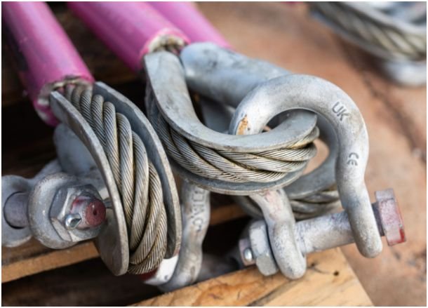
The familiar formula is:
SWL = Minimum Breaking Strength ÷ Safety Factor
It helps explain how to calculate safe working load for film rigging, but it needs context. Minimum Breaking Strength, or MBS, describes failure strength. Working Load Limit, or WLL, is the maximum rated working load under specified conditions.
For commercial lifting gear, I treat the marked WLL as controlling. I never divide MBS by a smaller safety factor to “upgrade” that rating. Sling capacity can also change with hitch type, loading angle, configuration, and operating conditions. OSHA requires rated-capacity information for sling configurations, while manufacturer guidance likewise treats angle and hitch as capacity factors.
| Term | What it means | How I use it |
| MBS | Minimum failure strength | Only with the correct design basis |
| Design factor | Strength-to-working-load ratio | Follow the applicable standard |
| WLL/SWL | Permitted working load | Starting capacity ceiling |
| Suspended load | Everything carried by the rig | Add it before checking capacity |
Count the Load Before You Count the Hardware
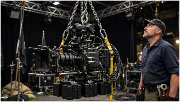
My next step in how to calculate safe working load for film rigging is totaling everything suspended.
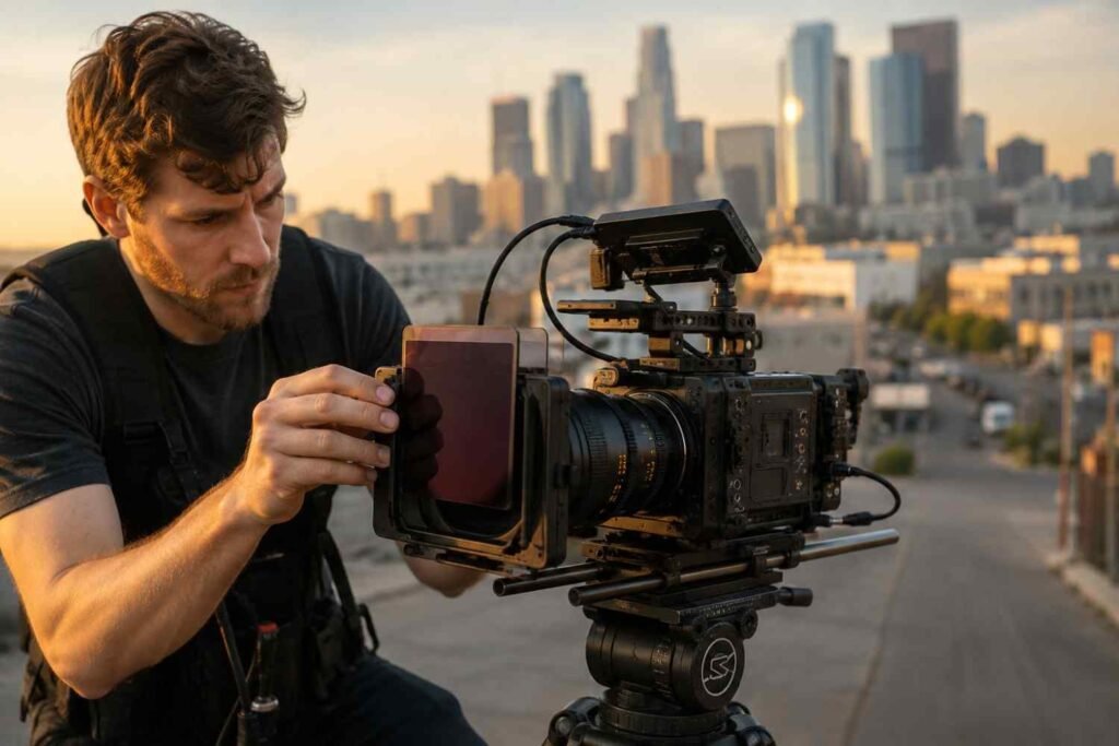
I include the camera, lens, remote head, carriage, batteries, motors, brackets, cable weight, safety hardware, and hanging rigging equipment.
This is more than bookkeeping. ETCP’s theatre-rigger examination content separately identifies breaking strength, design factors, WLL, center of gravity, object weight, and load distribution as core rigging knowledge. Review camera rigging case study to know how to execute the process while maintaining the safety standards.
A Quick Film-Rig Example
Suppose my hypothetical suspended package contains:
80 lb camera and lens + 160 lb remote head + 220 lb carriage + 40 lb cabling + 100 lb mounting and rigging hardware.
Total suspended load = 600 lb
That 600 pounds is only the static starting point.
It does not mean every sling carries 300 pounds. It also does not prove that every shackle, hoist, mounting point, or structural connection can support the system.
MBS ÷ Safety Factor Is a Check, Not a Shortcut
Suppose a component has an MBS of 10,000 pounds and the applicable design basis requires an 8:1 factor.
10,000 ÷ 8 = 1,250 lb
That arithmetic helps demonstrate how to calculate safe working load for film rigging. It does not establish an approved 1,250-pound WLL for an unknown or unmarked component.
This distinction is easy to miss.
There is no single safety-factor number that applies to every film rig. ESTA maintains separate entertainment standards covering powered hoist systems, electric chain hoists, rigging support points, performer flying, and other applications.
That means I would not automatically assign 5:1, 8:1, or 10:1 simply because a load is being used on a film set. The relevant equipment documentation, standard, engineered design, and operating conditions determine the correct requirement.
If a performer is supported or flown, ordinary camera-rigging calculations are not enough. ANSI E1.43-2025 specifically establishes requirements for performer flying systems including camera-rigging safety guidance.
The Angle Problem Gets Expensive Fast
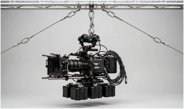
A straight vertical sling is easy to understand. A two-leg bridle changes the numbers.
For an equal, symmetrical two-leg bridle, where θ is measured above horizontal:
Leg tension = Total load ÷ (2 × sin θ)
That relationship matters whenever I work through how to calculate safe working load for film rigging because tension rises as the bridle gets flatter.
| Angle above horizontal | Load Angle Factor | Each leg with 600 lb |
| 90° | 1.000 | 300 lb |
| 60° | 1.155 | 347 lb |
| 45° | 1.414 | 424 lb |
| 30° | 2.000 | 600 lb |
The 45-degree example catches people.
The two sling legs do not simply divide 600 pounds into two 300-pound loads. Each leg carries about 424 pounds.
At 30 degrees, each leg carries roughly 600 pounds, equal to the entire suspended weight.
Columbus McKinnon notes that angle affects sling WLL, and OSHA provides rated-load guidance based on sling type and configuration.
I also write down the angle convention. Confusing an angle measured from horizontal with one measured from vertical can produce the wrong answer.
The Weakest Link Is Usually Not the Rope
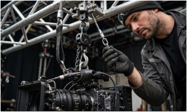
A rig does not inherit the capacity of its strongest component.
For me, how to calculate safe working load for film rigging always comes back to the lowest valid capacity anywhere in the load path.
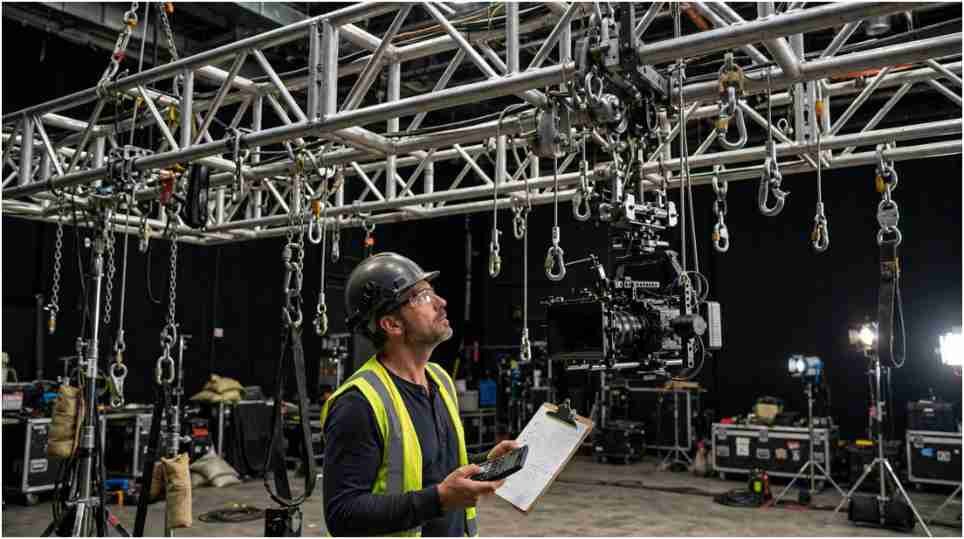
I check the structural support, sling, shackle, hoist, truss, clamp, mounting plate, and final camera attachment. Columbus McKinnon advises basing a rigging plan around the lowest-rated component and notes that loading angle can reduce a shackle’s usable capacity.
The support point deserves the same scrutiny.
ESTA’s ANSI E1.56-2026 addresses permanent entertainment rigging support points, including their design, fabrication, installation, inspection, and documentation. ETCP also expects entertainment riggers to work within building load limitations.
A 2,000-pound sling attached to an unknown structural point does not create a 2,000-pound rig.
Camera Movement Makes Static Math Expire
Static weight only describes a stationary load.
Starting, accelerating, braking, swinging, or suddenly stopping a camera changes the forces passing through the rig.
I would not use a blanket rule that every shock load equals three times static weight. There is no universal multiplier. Manufacturer guidance warns that rapidly applied loads can create dangerous overload conditions.
Consider a simplified vertical example.
A 600-pound load accelerating upward at 0.5 g produces an idealized force of:
Dynamic force ≈ static weight × (1 + acceleration/g)
600 × 1.5 = 900 lb
That is 900 pounds before applying bridle geometry or checking individual components.
Real camera systems become more complicated. Braking distance, rope elasticity, pendulum movement, drive behavior, and sudden stops can affect peak forces. ESTA also maintains specific standards for powered entertainment hoist systems rather than treating them as simple static suspensions.
This is where calculation software, manufacturer data, a qualified entertainment rigger, or a structural engineer may become necessary.
My Two-Pass Pre-Lift Check
When I review how to calculate safe working load for film rigging, I use two passes.
Pass one finds the static forces. Pass two asks what happens when the real rig starts moving.
| Check | Question I ask |
| Weight | Did I include every suspended component? |
| Rating | Is every WLL known and valid for its configuration? |
| Geometry | Did I calculate bridle angles and load distribution? |
| Weakest link | What is the lowest adjusted capacity? |
| Motion | Can acceleration, braking, swing, or shock raise force? |
| Structure | Is the support rated for the real load direction? |
This is why how to calculate safe working load for film rigging is better treated as a load-path calculation than a rope-strength calculation.
If one number is unknown, I do not round upward and hope for margin. The missing information needs to come from the manufacturer, venue, qualified rigger, or engineer.
Frequently Asked Questions
1. How do you calculate SWL from minimum breaking strength?
Divide the MBS by the applicable design factor, but never use the result to override a manufacturer-marked WLL or rated capacity.
2. What safety factor should I use for film rigging?
There is no universal ratio for every film rig; use the manufacturer requirement, applicable ANSI/ESTA standard, engineered design, and actual loading conditions.
3. How do sling angles change safe working load?
Flatter sling angles increase tension in each leg, which can reduce usable rigging capacity even though the suspended object’s weight never changes.
4. What is the safest way to learn how to calculate safe working load for film rigging?
Start with manufacturer WLL data, calculate geometry, identify the weakest component, then refer dynamic, structural, unusual, or performer-supporting systems to qualified personnel.
The Camera Can Wait. The Load Math Cannot
My rule for how to calculate safe working load for film rigging is simple: start with rated data, not optimism.
I add the complete suspended load. Then I calculate real leg forces, identify the weakest adjusted component, check the support point, and account for movement.
Before a rig leaves the ground, I would put its weight, WLLs, hitch types, angles, structural rating, and dynamic assumptions on one load sheet.
If one critical number is missing, that is the next number to find. Not the one to guess.