



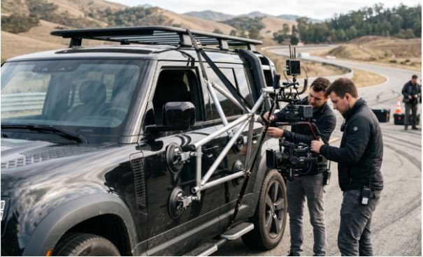
Outdoor Film Shoot Camera Rigging Case Study Guide

Taking a cinema camera outdoors at speed exposes every weakness in the mounting system. In this outdoor film shoot camera rigging case study, I examine how our crew stabilized a camera on a sports car traveling at 90 km/h and then transferred another camera from a robotic arm to a handheld operator during one uninterrupted shot.

Both setups taught me the same lesson: electronic stabilization cannot rescue a flexible structure. We first had to control geometry, vibration, weight, power, wind, and failure risk.

Project Overview: Two Shots, Two Different Rigging Problems

The first sequence required hood-level and wheel-level views of a sports car on a controlled asphalt track. The camera needed to remain stable under engine vibration, tire movement, aerodynamic pressure, and rapid directional changes.

The second sequence was a four-minute continuous tracking shot. It started above an open-top double-decker bus and ended at narrow street level. The camera had to move between three support systems without stopping the recording.

Although the shots looked very different, both relied on three principles:

Mechanical triangulation created rigidity. Independent safety connections protected the crew. Environmental planning prevented wind, sunlight, or power problems from disrupting the shot.

Case 1: Building a High-Speed Vehicle Camera Rig
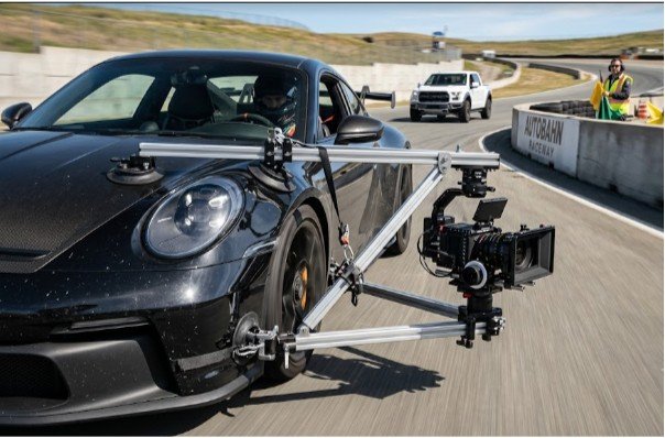
Case 1 Building a High-Speed Vehicle Camera Rig

The vehicle sequence used a Sony VENICE 2 camera with the VENICE Extension System. Sony designed the extension system to separate the compact sensor block from the main camera body while preserving image quality. That gave us more freedom to reduce the size and weight carried at the mounting point.

Creating a Triangulated Speed-Rail Foundation

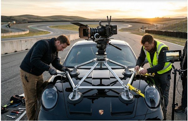
We built the base from 1.5-inch aluminum speed rail. Short barrel crosses and swivel tees connected the rails into a rigid lattice across the hood and lower chassis.

Two 10-inch industrial vacuum cups created the upper attachment points. A unibody frame clamp connected the lower section to structural steel beneath the vehicle.

This was not simply a collection of strong mounts. Their position mattered more than their individual ratings.

A long unsupported rail behaves like a lever. Even a small movement near its anchor becomes visible at the camera. We therefore added a secondary support above the camera’s center of mass. That rail formed a triangle with the primary arm and vehicle attachment.

This approach limited vertical whip and twisting movement. Anyone researching vehicle-mounted camera rigging should treat triangulation as the starting point, not a final correction.

Reducing Vibration at the Camera

The rigid frame solved large structural movement, but it could not absorb every high-frequency vibration. Engine harmonics, drivetrain movement, and tire contact produced fine jitter that reached the camera.

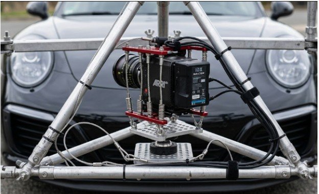
We placed a wire-rope isolator between the rail structure and camera plate. A ball-mounted cheese plate allowed us to level the horizon without rebuilding the complete frame.

The lighter VENICE sensor block also lowered the payload’s center of mass. That reduced leverage against the isolator and mounting arms.

The order was critical. We created a rigid base first, then introduced controlled isolation close to the camera. Placing soft isolation beneath a flexible arm would have allowed the entire assembly to oscillate.

Adding Independent Safety Redundancy

Vacuum cups were primary anchors, but we never treated them as permanent mechanical connections. Temperature changes, surface contamination, panel flex, or a damaged seal can reduce holding pressure.

We installed high-tensile endless ratchet straps from the camera basket to separate structural points near the engine frame bay and wheel arches. The safety lines did not share the same failure path as the suction mounts.

That independence matters. Adding two safety connections to the same weak panel does not create true redundancy.

OSHA advises employers to establish and enforce vehicle-safety procedures rather than treating road incidents as unavoidable. Transportation incidents also remain a major source of occupational fatalities in the United States.

Testing the Rig Before Reaching Full Speed

Our most useful original finding came from staged testing. We did not move directly from installation to the target speed.

We began with a static inspection. The team checked fasteners, cable clearance, camera movement, focus control, monitoring, suction pressure, and safety straps.

The driver then completed a walking-speed pass. After stopping, we marked the position of key connectors and inspected the rig for rotation, cable movement, loose hardware, or fresh contact marks.

We increased speed in controlled stages while reviewing footage for horizon drift, rolling-shutter distortion, focus inconsistency, frame vibration, and reflections.

One support arm appeared secure during the static test but showed slight movement over sharp surface changes. We adjusted its angle before the high-speed pass. That staged process found a weakness that hand pressure alone did not reveal.

Case 2: Rigging a Continuous Multi-Terrain Oner
Taking a cinema camera outdoors at speed exposes every weakness in the mounting system. In this outdoor film shoot camera rigging case study, I examine how our crew stabilized a camera on a sports car traveling at 90 km/h and then transferred another camera from a robotic arm to a handheld operator during one uninterrupted shot. Both setups taught me the same lesson: electronic stabilization cannot rescue a flexible structure. We first had to control geometry, vibration, weight, power, wind, and failure risk. Project Overview: Two Shots, Two Different Rigging Problems The first sequence required hood-level and wheel-level views of a sports car on a controlled asphalt track. The camera needed to remain stable under engine vibration, tire movement, aerodynamic pressure, and rapid directional changes. The second sequence was a four-minute continuous tracking shot. It started above an open-top double-decker bus and ended at narrow street level. The camera had to move between three support systems without stopping the recording. Although the shots looked very different, both relied on three principles: Mechanical triangulation created rigidity. Independent safety connections protected the crew. Environmental planning prevented wind, sunlight, or power problems from disrupting the shot. Case 1: Building a High-Speed Vehicle Camera Rig The vehicle sequence used a Sony VENICE 2 camera with the VENICE Extension System. Sony designed the extension system to separate the compact sensor block from the main camera body while preserving image quality. That gave us more freedom to reduce the size and weight carried at the mounting point. Creating a Triangulated Speed-Rail Foundation We built the base from 1.5-inch aluminum speed rail. Short barrel crosses and swivel tees connected the rails into a rigid lattice across the hood and lower chassis. Two 10-inch industrial vacuum cups created the upper attachment points. A unibody frame clamp connected the lower section to structural steel beneath the vehicle. This was not simply a collection of strong mounts. Their position mattered more than their individual ratings. A long unsupported rail behaves like a lever. Even a small movement near its anchor becomes visible at the camera. We therefore added a secondary support above the camera’s center of mass. That rail formed a triangle with the primary arm and vehicle attachment. This approach limited vertical whip and twisting movement. Anyone researching vehicle-mounted camera rigging should treat triangulation as the starting point, not a final correction. Reducing Vibration at the Camera The rigid frame solved large structural movement, but it could not absorb every high-frequency vibration. Engine harmonics, drivetrain movement, and tire contact produced fine jitter that reached the camera. We placed a wire-rope isolator between the rail structure and camera plate. A ball-mounted cheese plate allowed us to level the horizon without rebuilding the complete frame. The lighter VENICE sensor block also lowered the payload’s center of mass. That reduced leverage against the isolator and mounting arms. The order was critical. We created a rigid base first, then introduced controlled isolation close to the camera. Placing soft isolation beneath a flexible arm would have allowed the entire assembly to oscillate. Adding Independent Safety Redundancy Vacuum cups were primary anchors, but we never treated them as permanent mechanical connections. Temperature changes, surface contamination, panel flex, or a damaged seal can reduce holding pressure. We installed high-tensile endless ratchet straps from the camera basket to separate structural points near the engine frame bay and wheel arches. The safety lines did not share the same failure path as the suction mounts. That independence matters. Adding two safety connections to the same weak panel does not create true redundancy. OSHA advises employers to establish and enforce vehicle-safety procedures rather than treating road incidents as unavoidable. Transportation incidents also remain a major source of occupational fatalities in the United States. Testing the Rig Before Reaching Full Speed Our most useful original finding came from staged testing. We did not move directly from installation to the target speed. We began with a static inspection. The team checked fasteners, cable clearance, camera movement, focus control, monitoring, suction pressure, and safety straps. The driver then completed a walking-speed pass. After stopping, we marked the position of key connectors and inspected the rig for rotation, cable movement, loose hardware, or fresh contact marks. We increased speed in controlled stages while reviewing footage for horizon drift, rolling-shutter distortion, focus inconsistency, frame vibration, and reflections. One support arm appeared secure during the static test but showed slight movement over sharp surface changes. We adjusted its angle before the high-speed pass. That staged process found a weakness that hand pressure alone did not reveal. Case 2: Rigging a Continuous Multi-Terrain Oner The second part of this outdoor film shoot camera rigging case study involved a continuous four-minute shot. The camera began above a bus, moved away from a robotic arm, and finished with a handheld operator at street level. The challenge was not only stabilization. Every transition had to preserve camera orientation, power, monitoring, and operator control. Starting with an Elevated Robotic Camera A DJI Ronin 4D was attached to a custom robot plate on a motion-control arm. DJI combines imaging, four-axis stabilization, focusing, and wireless transmission within the Ronin 4D platform. The full standard configuration weighs about 4.67 kilograms before adding a lens or storage card. The robotic arm carried the camera above the bus deck for the opening view. Before movement, we checked the arm’s complete travel path for railings, performers, signage, overhead hazards, and emergency stopping clearance. Because crew members were working around an elevated platform, fall exposure also formed part of the risk assessment. OSHA requires employers to protect workers from falls at elevated work areas under the rules applicable to that workplace. Designing the Quick-Release Transition The camera connected to the robot plate through Mitchell mount quick-release risers. These created a repeatable handoff point for the grip team. We rehearsed the release with the camera powered down. Each crew member had one defined responsibility: stabilize the camera, release the mount, control cables, or confirm clearance. The operator did not take the full load until the grip holding the camera gave a clear verbal signal. This prevented two people from moving the assembly in opposite directions. Finishing the Shot at Street Level After uncoupling, the camera moved into a handheld configuration with dual side grips and a mechanical body vest. The grips gave the operator three physical contact points. The vest transferred part of the load away from the arms, which helped maintain framing during the final street-level movement. The handoff worked because the camera package remained compact. We avoided rebuilding accessories during the shot and kept the center of gravity close to the operator. Managing Wind, Power, Sunlight, and Exterior Conditions Outdoor camera rigging fails when crews focus only on the mount. Wind, battery changes, cable routing, and sunlight can alter the entire setup. Reducing Wind Resistance At bus height, crosswinds created pressure against the lens and matte box. We used a lightweight carbon-fiber clip-on matte box rather than a heavier rod-supported assembly. The clip-on configuration reduced front-heavy mass and limited the surface area exposed to wind. It also shielded the lens from flare without adding another long rail structure. Consolidating Camera Power We powered the camera, wireless transmitter, and follow-focus motors through one V-Lock battery plate and a D-Tap distribution loom. A shared system reduced accessory batteries and simplified hot-swapping. It also made the package easier to inspect because fewer batteries, chargers, and loose cables moved with the camera. However, consolidated power creates one potential failure point. We therefore tested total current demand, secured every connector, carried a matched replacement battery, and placed the battery where it would not disturb balance. Planning Around the Sun Path We mapped the planned camera direction against the sun’s movement before rigging. This helped us choose lens filtration, matte-box orientation, bus position, and performance timing. Sun-path planning also reduced last-minute adjustments. Changing a camera angle after building a complex rail system can affect balance, wind exposure, reflections, and safety clearance. Technical Lessons from Both Camera Rigging Setups This outdoor film shoot camera rigging case study produced five practical lessons. First, geometry must come before electronics. A gimbal can correct camera orientation, but it cannot turn a flexible base into a rigid one. Second, every primary mount needs an independent backup connected to a different structural point. Third, lower payload weight improves more than operator comfort. It reduces leverage, vibration, transition effort, and stress on each connection. Fourth, test movement in stages. Static pressure cannot reproduce road vibration, wind load, braking force, or sharp directional changes. Finally, simplify the complete camera ecosystem. Lightweight accessories, shared power, controlled cable paths, and repeatable quick releases make complex outdoor work safer and faster. Frequently Asked Questions 1. How do you stabilize a camera rig during an outdoor vehicle shoot? Build a triangulated structural base first, then add vibration isolation near the camera and test the setup at increasing speeds. 2. Are suction cups safe for professional vehicle camera mounting? They can serve as primary mounts when correctly rated and inspected, but they still need independent mechanical safety connections. 3. What is the best camera setup for a continuous outdoor tracking shot? Use a compact, balanced camera package with repeatable quick releases, stable monitoring, consolidated power, and rehearsed handoffs. 4. How should an outdoor cinema rig be tested before filming? Perform static, walking-speed, low-speed, and working-speed tests while inspecting fasteners, footage, cables, clearance, and backup restraints. Build the Structure Before Chasing the Shot The most impressive camera move means little if the supporting structure flexes, loosens, or forces the crew into an unsafe correction. My strongest takeaway from this outdoor film shoot camera rigging case study is simple: build for predictable failure, not perfect conditions. Triangulate the frame, reduce the payload, create independent backups, and test each new force gradually. Before the next exterior shoot, draw the rig as a load path. Mark every primary anchor, backup connection, transition point, cable route, and likely direction of force. That simple sketch can expose a weak design before the camera reaches the vehicle.
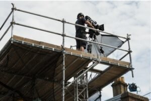
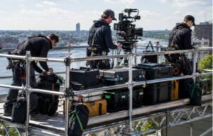
The second part of this outdoor film shoot camera rigging case study involved a continuous four-minute shot. The camera began above a bus, moved away from a robotic arm, and finished with a handheld operator at street level.

The challenge was not only stabilization. Every transition had to preserve camera orientation, power, monitoring, and operator control.

Starting with an Elevated Robotic Camera

A DJI Ronin 4D was attached to a custom robot plate on a motion-control arm. DJI combines imaging, four-axis stabilization, focusing, and wireless transmission within the Ronin 4D platform. The full standard configuration weighs about 4.67 kilograms before adding a lens or storage card.

The robotic arm carried the camera above the bus deck for the opening view. Before movement, we checked the arm’s complete travel path for railings, performers, signage, overhead hazards, and emergency stopping clearance.

Because crew members were working around an elevated platform, fall exposure also formed part of the risk assessment. OSHA requires employers to protect workers from falls at elevated work areas under the rules applicable to that workplace.

Designing the Quick-Release Transition

The camera connected to the robot plate through Mitchell mount quick-release risers. These created a repeatable handoff point for the grip team.

We rehearsed the release with the camera powered down. Each crew member had one defined responsibility: stabilize the camera, release the mount, control cables, or confirm clearance.

The operator did not take the full load until the grip holding the camera gave a clear verbal signal. This prevented two people from moving the assembly in opposite directions.

Finishing the Shot at Street Level

After uncoupling, the camera moved into a handheld configuration with dual side grips and a mechanical body vest.

The grips gave the operator three physical contact points. The vest transferred part of the load away from the arms, which helped maintain framing during the final street-level movement.

The handoff worked because the camera package remained compact. We avoided rebuilding accessories during the shot and kept the center of gravity close to the operator.

Managing Wind, Power, Sunlight, and Exterior Conditions

Managing Wind, Power, Sunlight, and Exterior Conditions

Outdoor camera rigging fails when crews focus only on the mount. Wind, battery changes, cable routing, and sunlight can alter the entire setup.

Reducing Wind Resistance

At bus height, crosswinds created pressure against the lens and matte box. We used a lightweight carbon-fiber clip-on matte box rather than a heavier rod-supported assembly.

The clip-on configuration reduced front-heavy mass and limited the surface area exposed to wind. It also shielded the lens from flare without adding another long rail structure.

Consolidating Camera Power

We powered the camera, wireless transmitter, and follow-focus motors through one V-Lock battery plate and a D-Tap distribution loom.

A shared system reduced accessory batteries and simplified hot-swapping. It also made the package easier to inspect because fewer batteries, chargers, and loose cables moved with the camera.

However, consolidated power creates one potential failure point. We therefore tested total current demand, secured every connector, carried a matched replacement battery, and placed the battery where it would not disturb balance.

Planning Around the Sun Path

We mapped the planned camera direction against the sun’s movement before rigging. This helped us choose lens filtration, matte-box orientation, bus position, and performance timing.

Sun-path planning also reduced last-minute adjustments. Changing a camera angle after building a complex rail system can affect balance, wind exposure, reflections, and safety clearance.

Technical Lessons from Both Camera Rigging Setups

This outdoor film shoot camera rigging case study produced five practical lessons.

First, geometry must come before electronics. A gimbal can correct camera orientation, but it cannot turn a flexible base into a rigid one.

Second, every primary mount needs an independent backup connected to a different structural point.

Third, lower payload weight improves more than operator comfort. It reduces leverage, vibration, transition effort, and stress on each connection.

Fourth, test movement in stages. Static pressure cannot reproduce road vibration, wind load, braking force, or sharp directional changes.

Finally, simplify the complete camera ecosystem. Lightweight accessories, shared power, controlled cable paths, and repeatable quick releases make complex outdoor work safer and faster.

Frequently Asked Questions

1. How do you stabilize a camera rig during an outdoor vehicle shoot?

Build a triangulated structural base first, then add vibration isolation near the camera and test the setup at increasing speeds.

2. Are suction cups safe for professional vehicle camera mounting?

They can serve as primary mounts when correctly rated and inspected, but they still need independent mechanical safety connections.

3. What is the best camera setup for a continuous outdoor tracking shot?

Use a compact, balanced camera package with repeatable quick releases, stable monitoring, consolidated power, and rehearsed handoffs.

4. How should an outdoor cinema rig be tested before filming?

Perform static, walking-speed, low-speed, and working-speed tests while inspecting fasteners, footage, cables, clearance, and backup restraints.

Build the Structure Before Chasing the Shot

The most impressive camera move means little if the supporting structure flexes, loosens, or forces the crew into an unsafe correction.

My strongest takeaway from this outdoor film shoot camera rigging case study is simple: build for predictable failure, not perfect conditions. Triangulate the frame, reduce the payload, create independent backups, and test each new force gradually.

Before the next exterior shoot, draw the rig as a load path. Mark every primary anchor, backup connection, transition point, cable route, and likely direction of force. That simple sketch can expose a weak design before the camera reaches the vehicle.

By Gavin Marsh

Gavin is a contributing writer at PhotoShip One, covering camera movement, cable-cam systems, rigging safety, and cinematography gear for production professionals. Gavin draws on real-world filming workflows to help readers navigate the technical and safety demands of modern production.

Leave a Reply

Your email address will not be published. Required fields are marked *