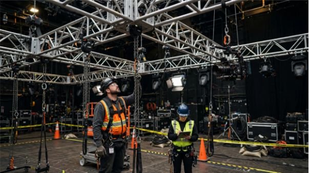






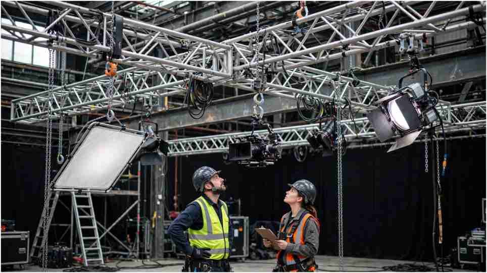
A film set overhead rigging load calculation can look safe on paper and still fail at one connection. The mistake I avoid is treating the rig as one total weight. The load travels through fixtures, clamps, truss, slings, shackles, hoists, anchors, and structure.
I treat each part as a separate limit. Calculate the force at that point, then compare it with the rating for that exact configuration. A safety factor is not a shortcut for tracing the load path.
Start With the Load That Is Actually Hanging
For any film set overhead rigging load calculation, I begin with dead load. Add fixtures, modifiers, frames, cable, power distribution, hardware, hoists, and any pipe or truss weight not already included in published data.
Wstatic = Σ fixtures + Σ modifiers + Σ cable + Σ hardware + other suspended equipment
I also check what the manufacturer has already counted. Prolyte states that the self-weight of its H30D truss is included in its published loading figures. Its figures are also limited to the stated span, orientation, support condition, and static-load case.
If I need to verify component limits first, I treat how to calculate safe working load for film rigging as a component-by-component question. OSHA’s construction rigging rule requires legible manufacturer load markings and says covered equipment must not exceed its marked safe working load. Which OSHA rule applies depends on the actual workplace and operation.
Bridle Angles Change the Force at the Ceiling
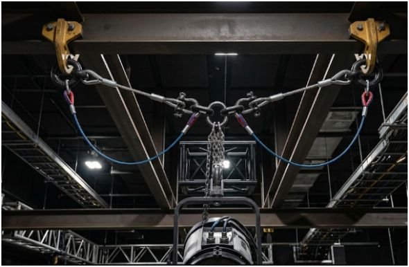
A film set overhead rigging load calculation changes when two points share one load. The load only splits 50/50 when the legs are vertical and the geometry is symmetrical.
Use the Two-Leg Bridle Equation
For a centered, symmetrical two-leg bridle:
T = W ÷ (2 × sin θ)
T is tension per leg, W is supported weight, and θ is the leg angle measured from horizontal.
| Horizontal leg angle | Tension per leg on 400 lb |
| 90° | 200 lb |
| 60° | 231 lb |
| 45° | 283 lb |
| 30° | 400 lb |
The table shows why shallow bridles demand attention. At 90 degrees, each leg carries half the load. At 30 degrees, each leg carries the entire 400-pound load.
OSHA guidance says alloy-chain sling angles below 30 degrees from horizontal should not be used unless recommended by the manufacturer or a qualified person. OSHA also calls for qualified analysis when multi-leg slings carry nonsymmetrical loads.
I keep safe rigging anchor points for film production as a separate check. A strong sling does not prove that a ceiling point, beam attachment, or building structure can accept the resulting forces. ESTA’s ANSI E1.56-2026 addresses permanent rigging support points attached to facility structures.
Point Loads and Uniform Loads Are Different Cases
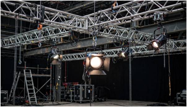
A common shortcut says a center point load is roughly half a truss’s uniformly distributed capacity. I do not use that rule.
The correct film set overhead rigging load calculation uses the manufacturer’s table for the exact truss, span, orientation, support arrangement, and load position.
Prolyte’s H30D data, for example, publishes separate capacities for uniformly distributed loads, center point loads, and loads positioned at thirds, fourths, and fifths. It also states that systems outside its specified single-span condition require individual structural calculation.
That matters on a film set because moving one large lamp toward midspan can change the governing structural condition without changing the total suspended weight.
Total pounds alone do not tell me enough. I need to know where those pounds are located.
Dynamic Loads in a Film Set Overhead Rigging Load Calculation
A static total becomes incomplete when a hoist starts, stops, travels, snags, or changes speed.
I do not apply a universal 2× or 3× shock multiplier to every film set overhead rigging load calculation. The required dynamic condition should come from applicable equipment documentation, engineering criteria, entertainment standards, or a qualified system designer.
OSHA’s sling guidance specifically instructs users not to shock-load slings.
Design factor, dynamic factor, and working load limit are also different concepts.
A working load limit is the usable rated capacity under specified conditions. A design factor forms part of the engineering relationship between rated capacity and material strength. Dynamic allowance addresses forces generated by movement or acceleration.
Mixing those terms into one arbitrary multiplier can produce a reassuring number that proves very little.
Powered systems deserve separate review. ESTA currently lists ANSI E1.6-1-2021 for powered hoist systems used in performance and theatrical production. Its scope does not cover the supporting structure to which the hoist is attached.
A Worked 360-Pound Film Set Example
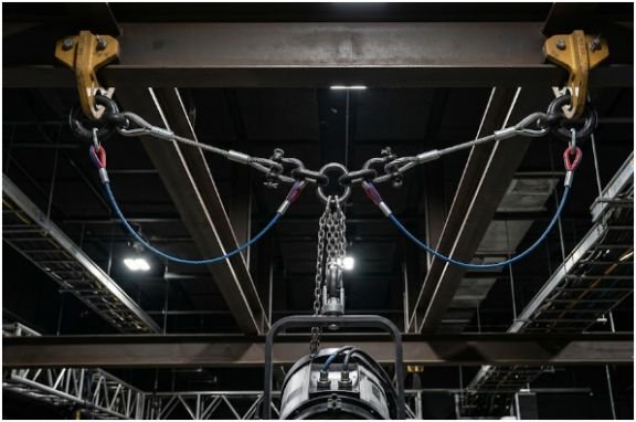
This is where a film set overhead rigging load calculation becomes easier to understand.
Assume my static lighting package totals 360 pounds. It hangs from a centered two-leg bridle at 45 degrees from horizontal.
Using the equation:
T = 360 ÷ (2 × sin 45°)
T ≈ 255 pounds per leg
The rig may weigh only 360 pounds, but each bridle leg is carrying about 255 pounds.
Now I compare that 255-pound force with the rating of each sling and shackle for its actual loading direction.
I do not simply read the number stamped on a shackle and stop there. Columbus McKinnon warns that loading angle and side loading can reduce effective shackle capacity. It also recommends planning around the lowest-rated component in the assembly.
Then I check the truss at the actual fixture positions.
After that come the hoist, upper attachment, rigging point, and supporting structure.
If the system moves, the approved dynamic load case must be considered before the final comparison.
For me, that is the core of a film set overhead rigging load calculation and for safety protocols, performing daily film rigging inspection.
My “weakest-path” worksheet uses only four columns:
| Component | Calculated force | Applicable WLL/limit | Margin |
| Bridle leg | 255 lb | Verified rating | Check |
| Shackle | Actual applied force | Configuration-specific WLL | Check |
| Truss | Actual load position | Manufacturer table | Check |
| Hoist/anchor | Calculated reaction | Rated/engineered limit | Check |
The table forces every assumption into the open.
The Five Checks I Want Before Anything Flies
Before a load leaves the deck, I want the film set overhead rigging load calculation to answer five questions:
- What is the complete suspended dead load?
- What force reaches each sling, shackle, hoist, anchor, and support?
- Do angles, hitches, side loads, or eccentric loads reduce capacity?
- Does the truss table match the actual span and load positions?
- Has a qualified person reviewed anything outside published ratings?
Inspection belongs beside the math.
OSHA’s construction rigging rule requires covered rigging equipment to be inspected before use on each shift. Defective equipment must be removed from service.
A perfect calculation cannot rescue a cracked fitting, damaged sling, unreadable identification tag, or incorrectly loaded connection.
Frequently Asked Questions
1. How do I calculate overhead rigging load on a film set?
Add all suspended weight, calculate force changes caused by geometry, and compare every load-path component with its applicable rated capacity.
2. What bridle angle is safest for film rigging?
There is no universal angle for every rig, but shallow angles increase leg tension and must remain within manufacturer or qualified-person limits.
3. Should I multiply film rigging weight by a 10:1 safety factor?
No universal 10:1 calculation applies to every system. Use the equipment WLLs, applicable standards, dynamic conditions, and engineering requirements for that rig.
4. What is the weakest-link rule in a film set overhead rigging load calculation?
The complete system cannot be treated as stronger than its lowest applicable component rating or structural capacity.
Make the Load Path Prove It
The best film set overhead rigging load calculation is not the page with the biggest safety-factor number. It is the one that models the real force path without shortcuts.
That is why I treat film set overhead rigging load calculation as a load-path check, not a multiplier exercise. I would rather see a 360-pound load traced through every bridle leg, shackle, truss point, hoist, and support than see a vague doubled load written at the top of a sheet.
The first method shows where the risk actually lives.
Before anything flies, verify the real equipment weights. Use the correct manufacturer tables. Inspect every rigging component. Send unusual geometry, dynamic systems, or structural questions to a qualified entertainment rigger or engineer.
The gear does not care how confident the spreadsheet looks.