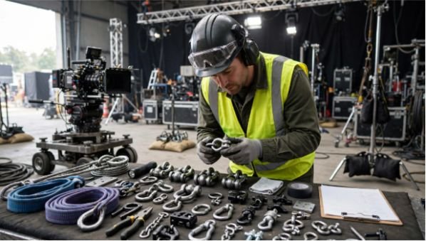






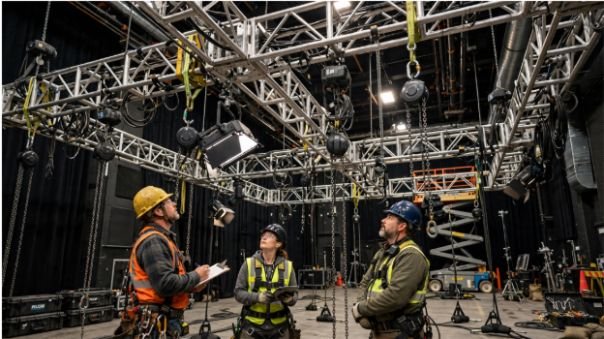
A rig can sit below a stage or studio’s total load capacity and still overload one attachment point. That is why I treat rigging load distribution for film sets as a point-by-point calculation, not a simple equipment-weight total.
The question is not only, “How much does the rig weigh?” I want to know exactly where that weight travels and how much force reaches every sling, shackle, hoist, truss section, clamp, and structural connection.
Why Rigging Load Distribution Matters on a Film Set
Film rigs often combine lighting fixtures, truss, motors, cable bundles, camera equipment, diffusion frames, scenic elements, and accessories. Their combined weight tells only part of the story.
A 4,000-pound assembly does not automatically place 1,000 pounds on four supports. Equipment position, center of gravity, sling geometry, and additional cable weight can make one point carry far more than another.
That distinction is fundamental to rigging load distribution for film sets.
OSHA requires slings to remain within their rated capacities and prohibits shock loading. Its construction rules also require rigging equipment to be inspected before use.
I therefore start every serious load review with the same principle: calculate the forces at individual points before comparing them with component ratings.
A broader film rigging safety checklist for production crews should then cover exclusion zones, communication, inspections, electrical hazards, and lift procedures around that calculated rig.
Trace the Complete Rigging Load Path
I map the load from the suspended object all the way to the supporting structure.
A typical overhead path might look like this:
Fixture → clamp → truss → sling → shackle → chain motor → beam connection → structural support.
Every item is part of the system. The overall capacity cannot exceed what the weakest relevant component or connection can safely support.
ASME B30.9 addresses sling selection, use, inspection, testing, and maintenance. ASME B30.26 covers detachable rigging hardware such as shackles, links, eyebolts, swivels, blocks, and load-indicating devices.
That is why rigging load distribution for film sets should be documented as a load path rather than recorded as one total number.
Sling Angles and Bridle Load Distribution
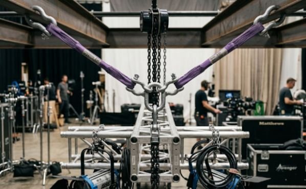
Angles can turn an apparently comfortable load into a demanding one.
As sling legs move farther away from vertical, each leg experiences greater tension. Manufacturer guidance also warns that angle of loading affects sling working load limits.
The Two-Leg Bridle Formula
For a symmetrical two-leg bridle:
T = W ÷ [2 × cos(θ)]
Where:
- T = tension in each bridle leg
- W = suspended load
- θ = each leg’s angle measured from vertical
Be careful with angle terminology. Some sling charts use the angle from horizontal instead. I always check which reference the manufacturer uses before applying a chart or formula.
Worked 1,000-Pound Bridle Example
Assume a centered 1,000-pound load.
| Angle from vertical | Approx. force per leg |
| 0° | 500 lb |
| 30° | 577 lb |
| 45° | 707 lb |
| 60° | 1,000 lb |
At 45 degrees, each leg sees about 707 pounds rather than 500 pounds.
At 60 degrees from vertical, each leg reaches roughly 1,000 pounds. The suspended object has not become heavier. Geometry has increased sling tension.
This is one of the calculations I consider essential when reviewing rigging load distribution for film sets.
Center of Gravity Changes Point Loads
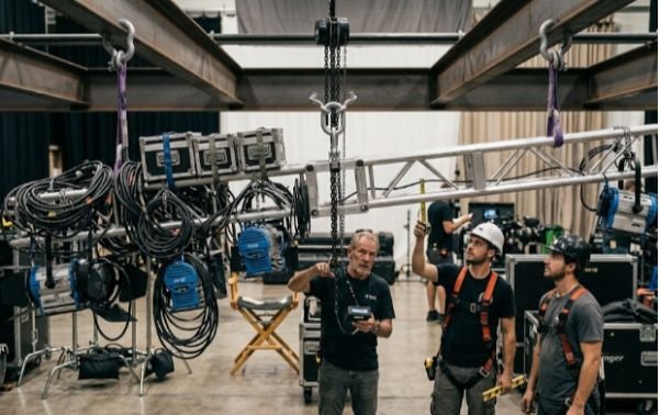
Perfectly symmetrical diagrams rarely survive contact with a real production package.
A large fixture may sit toward one end of the truss. A dimmer or power supply may sit on the other. Heavy feeder cable can shift the balance again.
The lifting arrangement should account for the load’s center of gravity. An off-center pick can produce swing and uneven loading as the system tries to settle beneath its lifting point.
My Point-Load Map Method
Before applying sling-angle factors, I calculate how the static weight reaches the supports.
Consider a simplified 1,200-pound rig supported at both ends of a 20-foot span. Its combined center of gravity lies eight feet from the left support.
For a simple two-support model:
Left reaction = 1,200 × (12 ÷ 20) = 720 lb
Right reaction = 1,200 × (8 ÷ 20) = 480 lb
The total remains 1,200 pounds, but the supports do not each carry 600 pounds.
That simple point-load map is my preferred sanity check. I first determine where the weight goes. Only then do I apply sling geometry, hardware limitations, and other forces.
A formal rigging risk assessment for film production should also examine what happens if the load shifts, a motor starts abruptly, weather changes, or an attachment behaves differently than planned.
Static Loads Are Only the Starting Number
Static weight describes equipment at rest. Production conditions can introduce additional forces.
Movement, acceleration, abrupt stopping, swinging loads, environmental forces, and changing geometry may increase loading. OSHA specifically prohibits shock loading of slings.
For outdoor production, large frames and overhead surfaces can also react strongly to wind. Those conditions require competent engineering judgment rather than a guessed percentage added to the dead load.
This distinction makes rigging load distribution for film sets especially important for moving lighting rigs, motorized systems, tracking equipment, stunt-related setups, and exterior stages.
WLL, Hardware Ratings and the Weakest Component
Working Load Limit, or WLL, is not the same thing as breaking strength.
I compare calculated loads against the marked or manufacturer-rated capacity for the actual configuration being used. Hitch type, sling angle, material, fittings, environmental conditions, and loading direction can affect usable capacity.
I also avoid assuming one universal design factor applies to every film rig. OSHA and ASME requirements vary by equipment and application, while manufacturers establish ratings and design factors for specific products.
Shackles deserve special attention. Angular or side loading can change stresses and may reduce usable capacity. Columbus McKinnon advises building a rigging plan around the lowest-rated component in the assembly.
Before relying on any label or stamped capacity, crews should know how to inspect rigging hardware before filming and remove damaged or defective equipment from service. OSHA’s construction sling standard requires daily pre-use inspection by a designated competent person.
Common Film Rigging Load Distribution Mistakes
Three mistakes repeatedly make otherwise sensible calculations unreliable.
Ignoring cable weight: Long power and data runs can noticeably shift a rig’s center of gravity. I include cables, accessories, hardware, and anything else the structure actually supports.
Treating total capacity as point capacity: A grid’s overall capacity does not prove that a specific beam, connection, hoist, or attachment point can carry a concentrated load.
Ignoring leverage: Extending equipment beyond a support creates a moment. Moving the same fixture farther from the support can significantly increase structural demand without changing its physical weight.
These problems explain why rigging load distribution for film sets must combine weight, position, geometry, and hardware ratings.
A Practical Load Distribution Check Before the Lift
I reduce the calculation to six questions before treating a rig as ready:
| Check | What I verify |
| Total load | All fixtures, truss, cable and hardware counted |
| COG | Combined balance point identified |
| Point loads | Expected force at each support calculated |
| Sling geometry | Angles included in tension calculations |
| WLL | Every component adequate for its actual loading |
| Condition | Slings, shackles, fittings and attachments inspected |
The paperwork should match the physical rig.
OSHA guidance requires workers to remain clear of suspended loads, and applicable construction rules restrict who may enter a fall zone during hoisting operations.
Calculating rigging load distribution for film sets therefore supports more than equipment selection. It also informs lift planning, exclusion zones, crew positioning, and emergency decisions.
FAQs
1. How do you calculate load distribution on film set rigging?
Find the total suspended weight, center of gravity and support reactions, then account for sling angles and individual hardware ratings.
2. Why does sling angle increase rigging tension?
As sling legs move farther from vertical, each leg must carry more tension to provide the required vertical supporting force.
3. Does a truss split its load equally between two motors?
Only when the load and geometry produce equal reactions; an offset center of gravity can make one motor carry considerably more.
4. What should be checked before suspending film equipment?
Confirm weight, COG, point loads, sling angles, WLL markings, attachment methods and the condition of every load-bearing component.
The Grid Doesn’t Care About Your Call Sheet
I never want schedule pressure to become part of the load calculation.
Good rigging load distribution for film sets comes from tracing forces all the way to the structure. Calculate the real weight. Locate the center of gravity. Determine individual point loads. Apply sling-angle effects. Then verify every component against its approved configuration and WLL.
If one number is uncertain, that is the number I resolve before the lift.
The smartest next step is simple: create a point-load map for the completed rig, have the appropriate qualified or competent personnel review it, and compare that map with the rig that actually exists overhead.